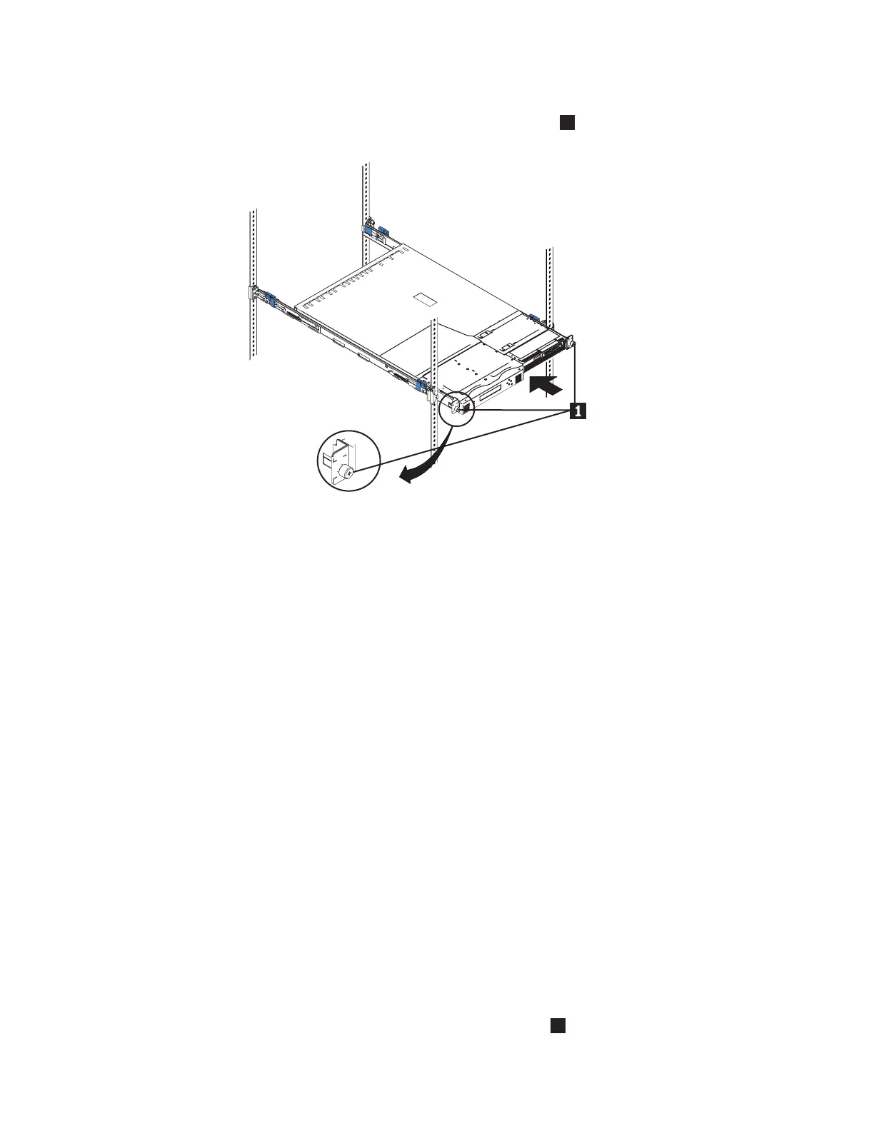
2. Slide the node fully into the rack.
3. Fully tighten the two captive thumbscrews (
1
in Figure 96).
4. Repeat this procedure for each SAN Volume Controller 2145-4F2 node that
needs to be installed.
Tip: If you have available space, leave a 1 space between each node to
improve the air circulation in the rack.
Connecting the SAN Volume Controller 2145-4F2 to the 2145
UPS-1U
Before you connect the SAN Volume Controller 2145-4F2 node to the 2145
uninterruptible power supply-1U (2145 UPS-1U), review the restrictions that exist
between the two systems.
Note: To make the SAN Volume Controller cluster more resilient to power failure,
the 2145 UPS-1Us can be connected to the redundant ac power switch. If a
redundant ac power switch is not used, connecting the two UPS units that
are powering an I/O group to different, independent electrical power
sources allows the SAN Volume Controller cluster to continue to operate
with reduced capacity if a single power source fails.
Before you begin this task, see the user’s cable connection table, which is described
in the IBM System Storage SAN Volume Controller: Planning Guide and is available at
http://www.ibm.com/storage/support/2145. Use this table to identify the 2145
UPS-1U to which this node is to be connected.
Perform the following steps to connect the SAN Volume Controller 2145-4F2 to the
2145 UPS-1U:
1. At the back of the SAN Volume Controller 2145-4F2, plug the combined power
and serial cable into the power connector (
2
in Figure 97 on page 134).
svc00081
Figure 96. Installing the SAN Volume Controller 2145-4F2 into a rack
Appendix B. SAN Volume Controller 2145-4F2 133
|
|
|
|
|
|
|
|
|
|
|
|
|
|
|
|
|
|
|
|

 Loading...


