Planning for power for server canister
Each enclosure is provided power through four power supplies. Either of the power modules can power
the enclosure independently if there is a loss of input power to the other power supply in the enclosure.
Plan to connect the power cords of the power supplies on the left side of the enclosures (when viewed
from the rear) to one power source, and connect the power cords of the power supplies on the right side
of the enclosures to another power source.
Attention: The power cords are the main power disconnect. Ensure that the socket outlets are
located near the equipment and are easily accessible.
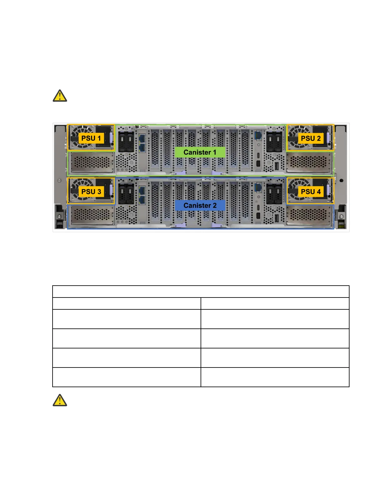
The following gure shows the rear view of an IBM Storage Scale System 6000. The power modules are
located on the sides of the IBM Storage Scale System 6000.
Figure 20. Rear view of an IBM Storage Scale System 6000
Planning for cable connections to PDUs
Each enclosure must be connected to a pair of power outlets by selecting appropriate feature codes while
ordering the system. The following table lists the feature codes of the power cords.
Table 16. Power cord feature codes
Feature codes Description
ELC5 Power cable - Drawer to IBM PDU (250V/10A)
C13/C20
END7 Power cord - Drawer to IBM PDU (250V/10A)
C13/C20
4558 Power cord - 4.3 m (14.1 ft), drawer to IBM PDU
(250 V/10 A) C13/C14
END8 Power cord - 3.0 m (9.8 ft), drawer to IBM PDU
(250 V/10 A) C13/C14
Attention: Ensure that sufcient power supply circuits are available to provide the total power
requirements of the equipment that is connected to each power supply circuit.
EMS node power planning
The following table lists the documentation that can be used as a reference while planning for power
requirements.
34
IBM Storage Scale System 6000: Hardware Planning and Installation Guide