213
Replacement Procedures and Illustrated Parts List
Ethernet Interface LEDs and DIP Switches
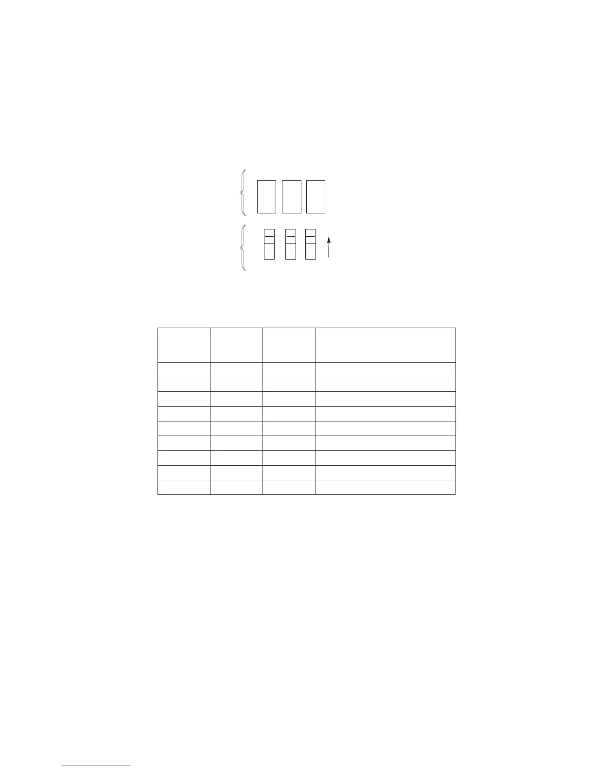
The Ethernet Interface has three LEDs and three DIP switches, as shown
below. These indicators and switches are adjacent to the data line
connectors. LED patterns are defined in the table below the illustration.
Status Indicator LEDs and DIP Switches
123
OFF
Grn Red Grn
STAT ERR NET
Status
Indicators
DIP
Switches
(Default is all
switches OFF,
as shown.)
LED Pattern Indications
STAT
(System
Status)
ERR
(System
Error)
NET
(Data to
Network)
Mode
ON OFF ON RAM Test
ON OFF OFF ROM Test
ON ON OFF EEPROM Test
OFF ON ON Network Interface Test
OFF OFF ON PRN1 Test
FLASH OFF FLASH Run Mode
FLASH ON FLASH Auto Reset Mode
FLASH FLASH OFF Firmware Panic
ON FLASH ON Hardware Exception
The Ethernet Interface Assembly has a self test and two internally controlled
modes:
Power-on Self Test: A seven stage power-on self test performs diagnostics
on the Ethernet Interface processor, RAM, ROM, EEPROM, parallel port, and
network interface. The STAT, ERR, and NET LEDs indicate which test is
currently in progress.
Run and Auto Reset Modes: Run Mode is the normal operating state of the
Ethernet Interface. Auto Reset mode is entered when the watchdog timer is
triggered and the Print Server resets itself. In either mode, the STAT LED
flashes differently depending on whether the unit IP address is configured.

 Loading...


