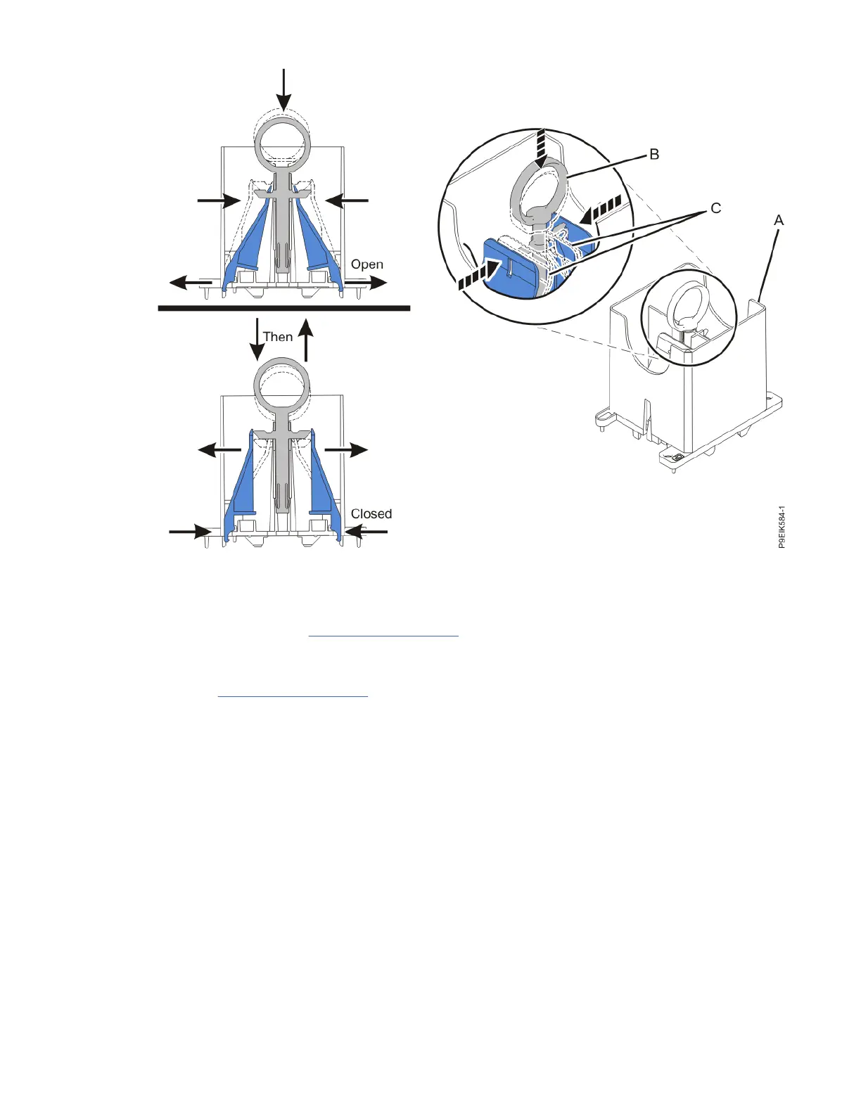
Figure 567. Ensuring that the removal tool is in the open position
b) Align the tool over the system processor module.
Ensure that the beveled edge on the tool aligns with the beveled edge of the system processor
module (C) as shown in Figure 568 on page 648.
c) Lower the tool over the system processor module.
Ensure that the two guide pins (A) insert into the alignment holes (B) on each side of the tool as
shown in Figure 568 on page 648.
System processor module
647

 Loading...