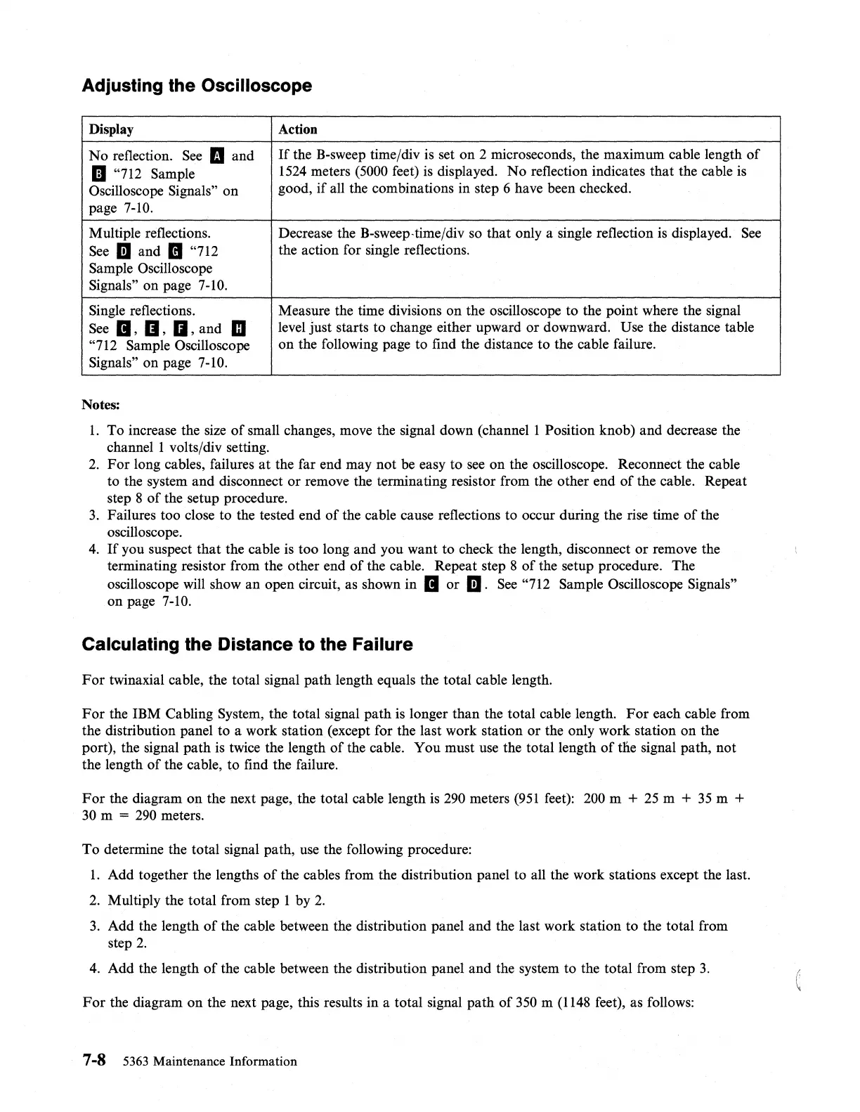
Adjusting the Oscilloscope
Display Action
No
reflection.
See
II
and
If
the B-sweep time/div is set
on
2 microseconds, the maximum cable length
of
II
"712 Sample
1524
meters (5000 feet)
is
displayed.
No
reflection indicates that the cable is
Oscilloscope
Signals" on
good,
if
all the combinations in step 6 have been checked.
page 7-10.
Multiple reflections. Decrease the B-sweep-time/div so that only a single reflection is displayed.
See
See
iii and
II
"712
the action for single reflections.
Sample Oscilloscope
Signals" on page 7-10.
Single reflections. Measure the time divisions
on
the oscilloscope to the point where the signal
See
II,
II,
II,
and m
level just starts to change either upward or downward. Use the distance table
"712 Sample Oscilloscope
on
the following page to find the distance to the cable failure.
Signals" on page 7-10.
Notes:
1.
To increase the size
of
small changes, move the signal down
(channell
Position knob) and decrease the
channel 1 volts/div setting.
2.
For
long cables, failures
at
the far end may not be easy to
see
on the oscilloscope. Reconnect the cable
to the system and disconnect
or
remove the terminating resistor from the other end
of
the cable. Repeat
step 8
of
the setup procedure.
3.
Failures too close to the tested end
of
the cable cause reflections to occur during the rise time
of
the
oscilloscope.
4.
If
you suspect that the cable is too long and you want to check the length, disconnect
or
remove the
terminating resistor from the other end
of
the cable. Repeat step 8
of
the setup procedure. The
oscilloscope will show an open circuit, as shown in
II
or
iii.
See
"712 Sample Oscilloscope Signals"
on page
7-10.
Calculating the Distance
to
the Failure
For
twinaxial cable, the total signal path length equals the total cable length.
For
the IBM Cabling System, the total signal path is longer than the total cable length.
For
each cable from
the distribution panel to a work station (except for the last work station
or
the only work station on the
port), the signal
path
is
twice the length
of
the cable. You must use the total length
of
the signal path, not
the length
of
the cable, to find the failure.
For
the diagram
on
the next page, the total cable length is 290 meters
(951
feet): 200 m +
25
m +
35
m +
30
m =
290
meters.
To
determine the total signal path, use the following procedure:
1.
Add together the lengths
of
the cables from the distribution panel to all the work stations except the last.
2.
Multiply the total from step 1 by
2.
3.
Add the length
of
the cable between the distribution panel and the last work station to the total from
step
2.
4.
Add the length
of
the cable between the distribution panel and the system
to
the total from step
3.
For
the diagram
on
the next page, this results in a total signal path
of
350 m
(1148
feet), as follows:
7-8
5363
Maintenance Information
 Loading...