v When one of the disk drawers is pulled out or not in the closed/latched position
v When one of the fan assemblies has failed or is removed from the enclosure
Note: To preserve the optimal airflow, do not remove a failed fan assembly FRU from the chassis until
you are ready to replace it with a new FRU.
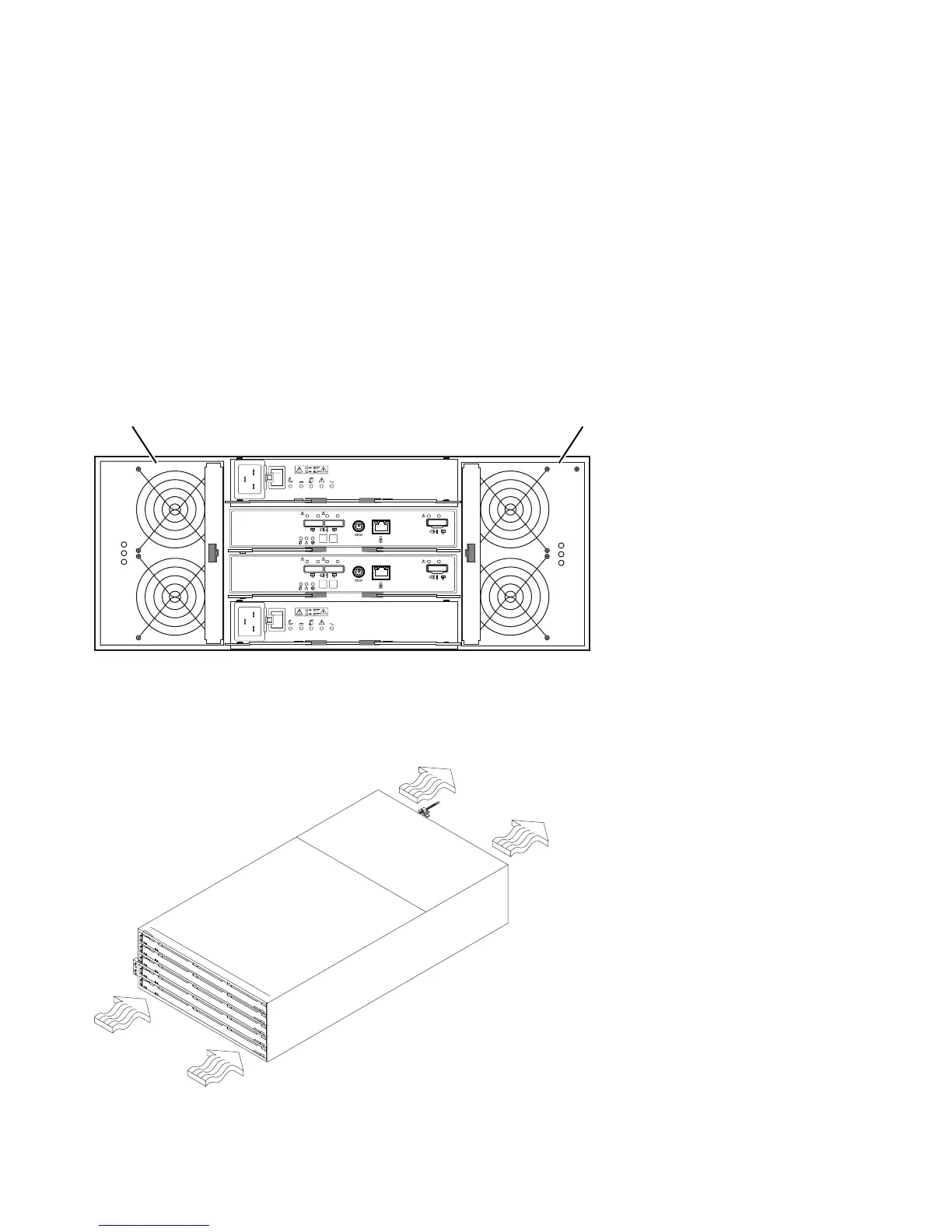
Figure 10 shows the location of the fan assemblies. See “Fan assembly LEDs” on page 76 for information
about the fan assembly status LEDs.
Note: Although both fan assemblies (left and right) are identical, they are seated in the enclosure in
opposite orientations. If the fan assembly cannot be fully inserted in the fan assembly bay, rotate it
180 degrees and reinsert it. In addition, there are notches on the top and bottom of the fan
assembly bay. Make sure that the slits on the top and bottom of the fan assembly line up with
these two notches before the fan assembly is fully inserted in the fan bay.
Figure 11 shows fan assembly airflow through the storage expansion enclosure.
dcsi0003
1
2
Lnk Lnk Lnk Lnk
ID/Diag
Lnk Lnk
8 8
1
2
Lnk Lnk Lnk Lnk
ID/Diag
Lnk Lnk
8 8
ACDC
2
1
I
O
ACDC
2
1
I
O
Fan unit A Fan unit B
Figure 10. Fan assembly components
Front
Back
dcsi0014
Figure 11. Storage expansion enclosure airflow
14 IBM System Storage DCS3700: Installation, User, and Maintenance Guide