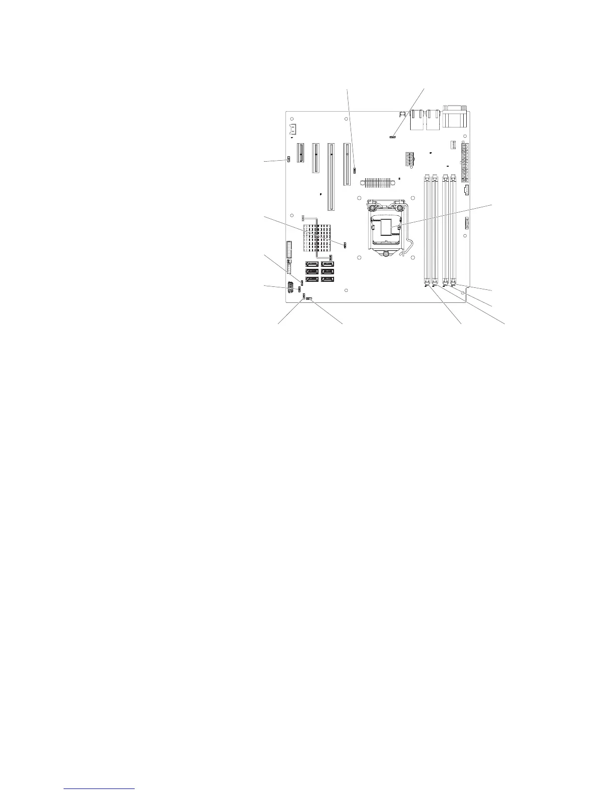
Clean CMOS
jumper (JP1)
BIOS boot backup
jumper (JP2)
ME recovery
jumper (JP8)
ME flash
override
jumper(JP9)
TPM physical
presence jumper
(JP10)
TPM initialization
jumper (JP11)
Low security_N
jumper (JP22)
IMM SPI half
ROM enable (JP12)
DIMM 1 slot
DIMM 2 slot
DIMM 3 slotDIMM 4 slot
Microprocessor
5. Remove any adapter that impede access to the boot block recovery jumper
(JP2) (see “Removing a ServeRAID adapter” on page 176).
6. Move the BIOS boot backup jumper (JP2) from pins 1 and 2 to pins 2 and 3 to
enable the UEFI recovery mode.
7. Reinstall any adapter that you removed before (see “Installing a ServeRAID
adapter” on page 178).
8. Reinstall the server cover (see “Installing the side cover” on page 167).
9. Reconnect the power cord and any cables that you removed.
10. Restart the server. The system begins the power-on self-test (POST).
11. Boot the server to an operating system that is supported by the firmware
update package that you downloaded.
12. Perform firmware update following the instructions in the firmware update
package readme file.
13. Turn off the server and disconnect all power cords and external cables, and
then remove the server side cover (see “Removing the side cover” on page
166).
14. Remove any adapter that impede access to the boot block recovery jumper
(JP2) (see “Removing a ServeRAID adapter” on page 176).
15. Move the BIOS boot backup jumper (JP2) from pins 2 and 3 back to the
primary position (pins 1 and 2).
16. Reinstall any adapter that you removed before (see “Installing a ServeRAID
adapter” on page 178).
17. Reinstall the server top cover (see “Installing the side cover” on page 167).
18. Reconnect the power cord and any cables that you removed.
19. Restart the server. The system begins the power-on self-test (POST). If this
does not recover the primary back, continue with the following steps.
20. Remove the server side cover (see “Removing the side cover” on page 166).
Chapter 3. Diagnostics 143

 Loading...


