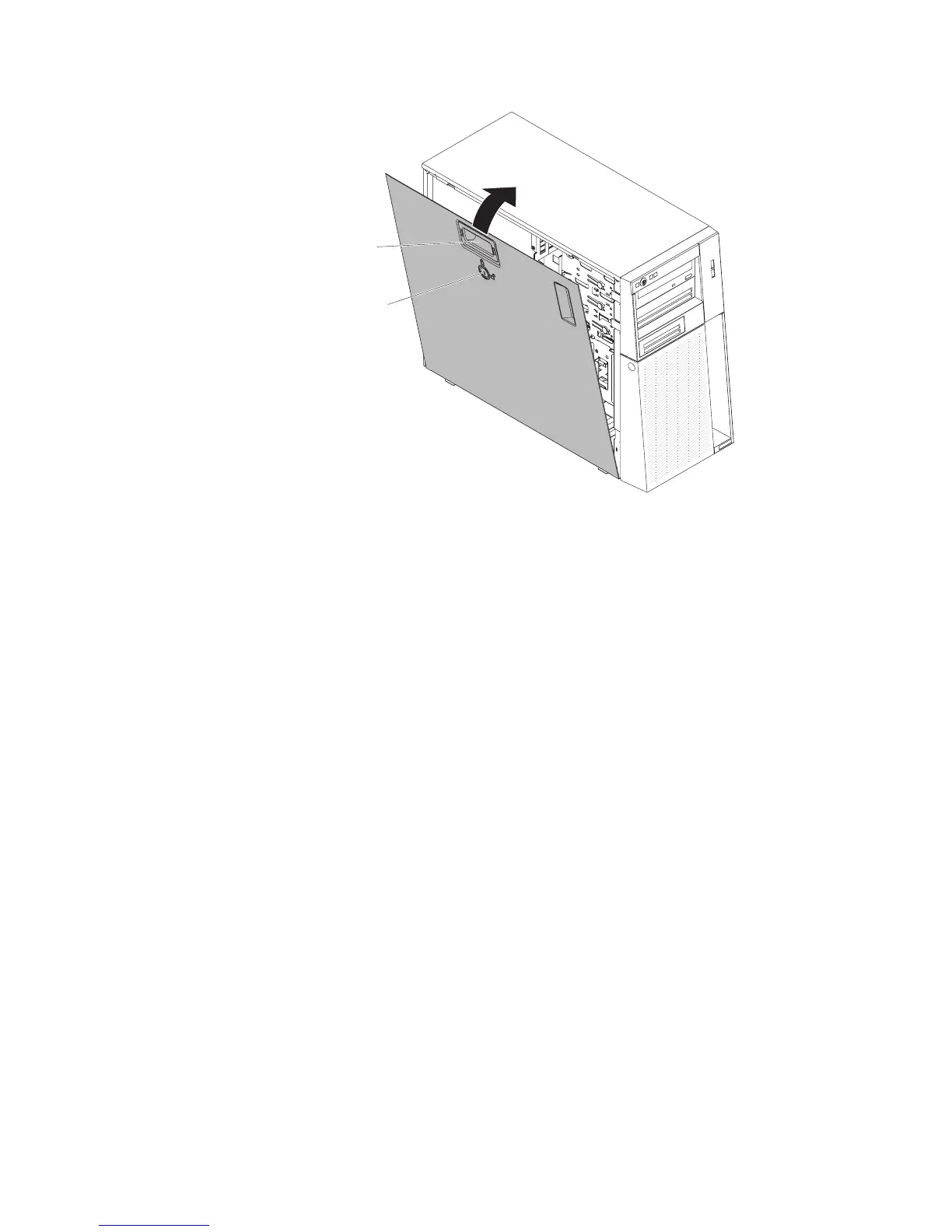
EasyManuals Logo

IBM System x3100 M4 Problem Determination And Service Guide

IBM System x3100 M4
332 pages
To Next Page IconTo Next Page
To Previous Page IconTo Previous Page
Page #189 background imageLoading...
Page #189 background image
Key lock
Cover-release
latch
4. Lock the side cover.
5. Reconnect the external cables and power cords; then, turn on the attached
devices and turn on the server.
Removing the bezel
This procedure applies only to 4U server models with non-hot-swap power supplies.
When you work with some devices on 4U server models with non-hot-swap power
supplies, such as the drives in bays 3 through 6, you must first remove the bezel to
access the devices.
To remove the bezel on 4U server models with non-hot-swap power supplies,
complete the following steps.
1. Read the safety information that begins on page vii and “Installation guidelines”
on page 163.
2. Open the bezel by pressing the button on the left edge of the bezel, and rotate
the left side of the bezel away from the server.
Chapter 5. Removing and replacing server components 169

Table of Contents

Other manuals for IBM System x3100 M4

Questions and Answers:

Question and Answer IconNeed help?

Do you have a question about the IBM System x3100 M4 and is the answer not in the manual?

IBM System x3100 M4 Specifications

General IconGeneral
MemoryUp to 32 GB DDR3 ECC UDIMM
Memory Slots4 DIMM slots
Form FactorTower
ChipsetIntel C202
Processor Sockets1
ProcessorIntel Xeon E3-1200 v2 series, Intel Pentium series, Intel Celeron series
StorageUp to 4x 3.5-inch
Power Supply350W
Hard Drive Bays4 x 3.5"
RAID SupportRAID 0, 1, 10
Network InterfaceGigabit Ethernet
Expansion Slots1 x PCIe 3.0 x16, 1 x PCIe 2.0 x4
Operating System SupportWindows Server, Red Hat Enterprise Linux, SUSE Linux Enterprise Server

Related product manuals