EasyManuals Logo

IBM System x3100 M4 Problem Determination And Service Guide

IBM System x3100 M4
332 pages
To Next Page IconTo Next Page
To Previous Page IconTo Previous Page
Page #37 background imageLoading...
Page #37 background image
Internal LEDs, connectors, and jumpers
The illustrations in this section show the connectors, light-emitting diodes (LEDs),
and switches on the system board. The illustrations might differ slightly from your
hardware.
Note: The connectors on the system board illustrations might vary slightly from
your system board, depending on your server model.
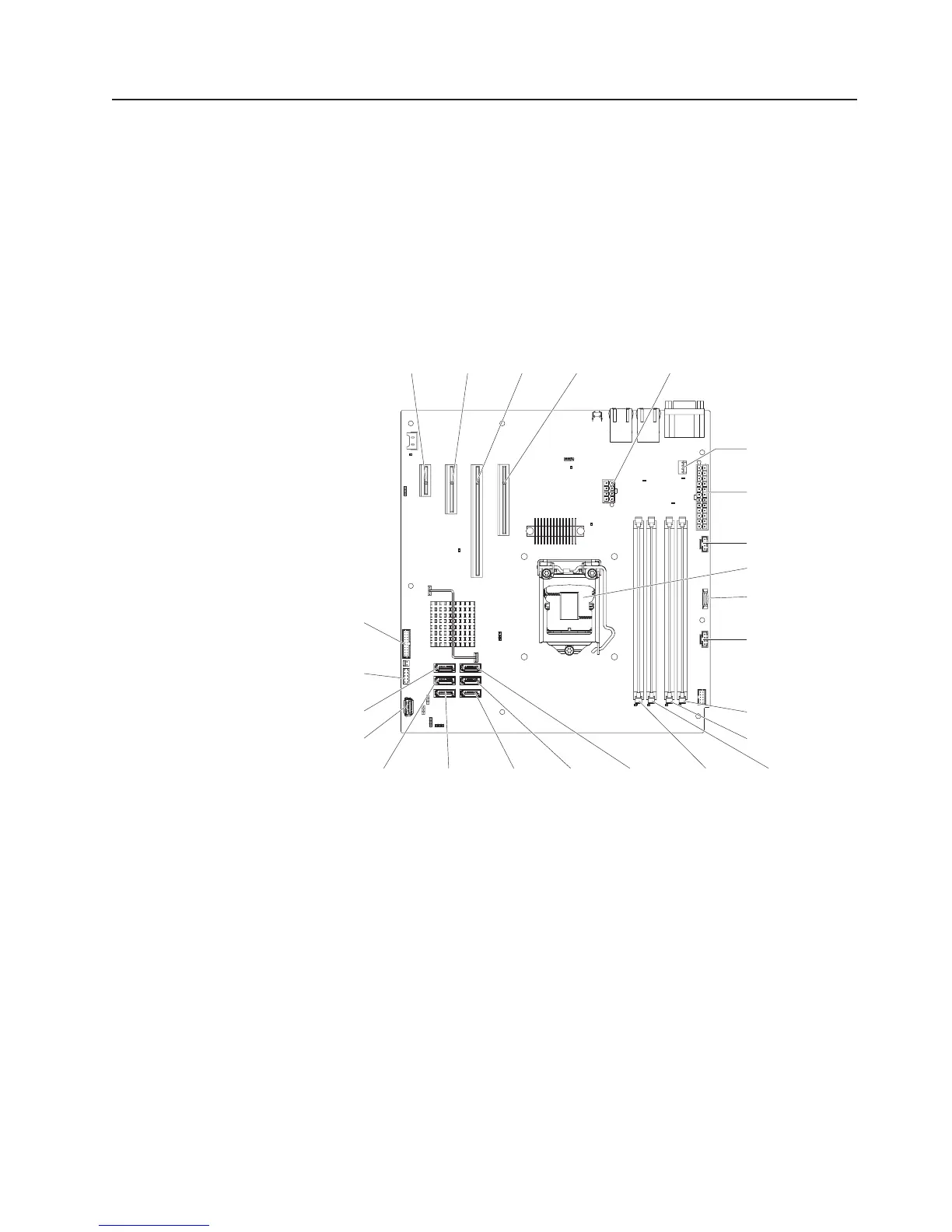
System-board internal connectors
The following illustration shows the internal connectors on the system board.
Battery
DIMM 1
DIMM 2
DIMM 3DIMM 4
SATA 2 SATA 1 SATA 0SATA 3SATA 4
SATA 5
Power 1
System fan
connector
PCI
slot 4
Microprocessor
Front USB
connector
Front-panel
connector
Power 2
USB tape drive
connector
PCI
slot 3
PCI
slot 2
PCI
slot 1
Power 3
Power 4
Chapter 2. Introduction 17

Table of Contents

Other manuals for IBM System x3100 M4

Questions and Answers:

Question and Answer IconNeed help?

Do you have a question about the IBM System x3100 M4 and is the answer not in the manual?

IBM System x3100 M4 Specifications

General IconGeneral
MemoryUp to 32 GB DDR3 ECC UDIMM
Memory Slots4 DIMM slots
Form FactorTower
ChipsetIntel C202
Processor Sockets1
ProcessorIntel Xeon E3-1200 v2 series, Intel Pentium series, Intel Celeron series
StorageUp to 4x 3.5-inch
Power Supply350W
Hard Drive Bays4 x 3.5"
RAID SupportRAID 0, 1, 10
Network InterfaceGigabit Ethernet
Expansion Slots1 x PCIe 3.0 x16, 1 x PCIe 2.0 x4
Operating System SupportWindows Server, Red Hat Enterprise Linux, SUSE Linux Enterprise Server

Related product manuals