Installing a simple-swap hard disk drive
This procedure applies only to 4U server models with non-hot-swap power supplies.
For 4U server models with non-hot-swap power supplies, the server supports up to
four 3.5-inch simple-swap SATA hard disk drives, which are accessible from the
front of the server. You must disconnect all power from the server before you
remove or install simple-swap drives. Before you install a simple-swap SATA hard
disk drive, read the following information:
To install a simple-swap SATA hard disk drive on 4U server models with
non-hot-swap power supplies, complete the following steps.
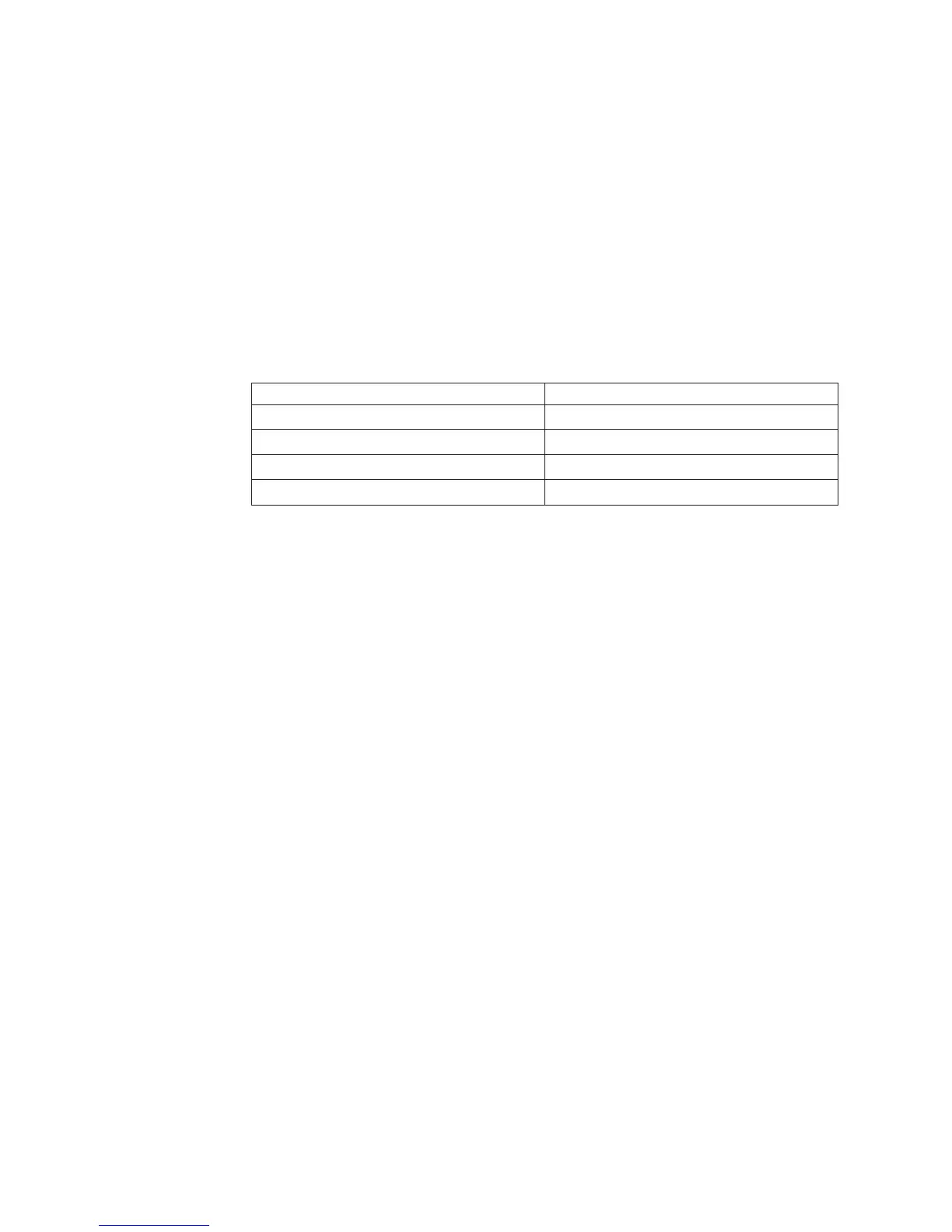
v Install the drives starting from the top bay to the bottom bay (bay 3, 4, 5, and
then 6). The following tables list the IDs of the hard disk drives:
Table 11. IDs of simple-swap drives
Drive bay HDD ID
30
41
52
63
v The simple-swap SATA hard disk drives connect to the SATA 0 through SATA 3
connectors on the system board as follows:
– System board end cable connector 0 connects to the SATA 0 connector on
the system board.
– System board end cable connector 1 connects to the SATA 1 connector on
the system board.
– System board end cable connector 2 connects to the SATA 2 connector on
the system board.
– System board end cable connector 3 connects to the SATA 3 connector on
the system board.
v
– Hard disk drive 0 connects to the SATA 0 connector on the system board.
– Hard disk drive 1 connects to the SATA 2 connector on the system board.
– Hard disk drive 2 connects to the SATA 1 connector on the system board.
– Hard disk drive 3 connects to the SATA 3 connector on the system board.
Note: Under RAID mode:
1. In uEFI setup menu:
v Drive 0 indicates hard disk drive 0.
v Drive 1 indicates hard disk drive 2.
v Drive 2 indicates hard disk drive 1.
v Drive 3 indicates hard disk drive 3.
2. In MegaRAID Storage Manager utility:
v Slot 0 indicates hard disk drive 0.
v Slot 1 indicates hard disk drive 2.
v Slot 2 indicates hard disk drive 1.
v Slot 3 indicates hard disk drive 3.
196 IBM System x3100 M4 Type 2582: Problem Determination and Service Guide

 Loading...


