Table 16. UDIMM population rule (continued)
DIMM connector 1 DIMM connector 2 DIMM connector 3 DIMM connector 4
Populated Empty Populated Empty
Populated Populated Populated Populated
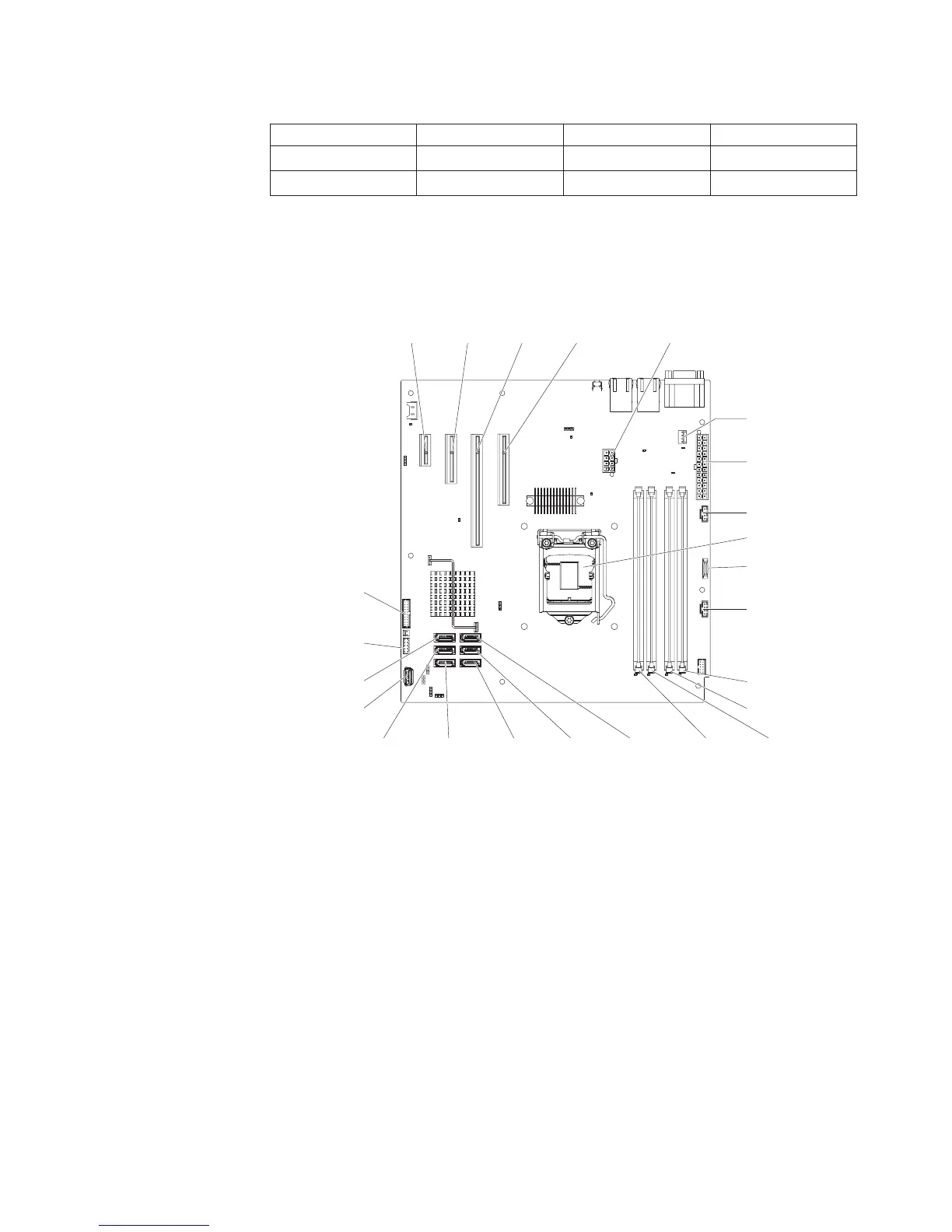
The following illustration shows the location of the DIMM connectors on the system
board.
Note: The illustrations in this document might differ slightly from your model.
Battery
DIMM 1
DIMM 2
DIMM 3DIMM 4
SATA 2 SATA 1 SATA 0SATA 3SATA 4
SATA 5
Power 1
System fan
connector
PCI
slot 4
Microprocessor
Front USB
connector
Front-panel
connector
Power 2
USB tape drive
connector
PCI
slot 3
PCI
slot 2
PCI
slot 1
Power 3
Power 4
Attention: Static electricity that is released to internal server components when
the server is powered on might cause the server to halt, which might result in the
loss of data. To avoid this potential problem, always use an electrostatic-discharge
wrist strap or other grounding system when you work inside the server with the
power on.
To install a DIMM on 4U server models with non-hot-swap power supplies, complete
the following steps. For the 5U server model with hot-swap power supplies (Model
name: 2582-F4x), please see the next sub-section.
1. Read the safety information that begins on page vii and “Installation guidelines”
on page 163.
2. Turn off the server and peripheral devices, and disconnect the power cords
and all external cables.
3. Carefully turn the server on its side so that it is lying flat, with the cover facing
up.
Attention: Do not allow the server to fall over.
4. Remove the side cover (see “Removing the side cover” on page 166).
5. Remove the air duct.
Chapter 5. Removing and replacing server components 205

 Loading...


