!3 MENU SWITCH [MENU] (p. 19)
➥ Push to change the set of functions assigned to
switches ([F-1] to [F-5]).
•Toggles the function display menu between M1
(Menu 1), M2 (Menu 2), M3 (Menu 3), D1 and D2.
➥ Hold down for 1 second to enter the Set mode.
Push to return to the previous screen display.
!4 NOISE REDUCTION LEVEL CONTROL [NR]
(innercontrol;p.77)
Rotate to adjust the DSP noise reduction level
when the noise reduction function is in use. Set for
maximum readability.
•Tousethiscontrol,rstpush[NR] (!5).
Increases
Decreases
!5 NOISE REDUCTION SWITCH [NR] (p. 77)
Push to turn DSP noise reduction ON or OFF.
•“NR”appearswhennoisereductionisON.
!6 SUB BAND TX/RX INDICATOR
Lights green when the squelch opens, or a signal is
receivedontheSUBBand;lightsredduringtrans-
mit in the satellite mode.
➥ Blinks green when an off-frequency signal is re-
ceived, depending on the “FM/DV Center Error”
option in the Set mode. (p. 162)
!7 SUB BAND RF GAIN CONTROL/
SQUELCH CONTROL [RF/SQL]
(outercontrol;p.44)
Rotate to adjust the RF gain and squelch threshold
level on the SUB Band.
The squelch stops noise output to the speaker
when no signal is received. (closed condition)
See o on page 2 for details.
!8
SUB BAND AF CONTROL [AF] (innercontrol;p.45)
Rotate to adjust audio output level to the speaker or
headphones on the SUB Band.
!9 MIC GAIN CONTROL [MIC GAIN] (p. 46)
Rotate to adjust the microphone gain.
•ThetransmitaudiotoneintheSSB,AMandFMmodescan
be independently adjusted in the tone control Set mode.
(p. 169)
✔ How to set the microphone gain.
Set the meter function to ALC. (p. 45) While speak-
ing at normal voice level, adjust the [MIC GAIN]
control so that in the SSB or AM modes, the ALC
meter swings within the ALC range.
Recommended level for
Icom microphones
IncreasesDecreases
@0 RF POWER CONTROL [RF POWER] (p. 46)
Rotate to continuously vary the RF output power.
IncreasesDecreases
Frequency band RF output power range
HF/50 MHz 2 to 100 W (AM: 2 to 30 W)
144 MHz 2 to 100 W
430 MHz 2 to 75 W
1200 MHz 1 to 10 W
@1 CW PITCH CONTROL [CW PITCH]
(outercontrol;p.49)
(Mode: CW)
Rotate to shift the received CW audio pitch and the
CW sidetone pitch without changing the operating
frequency.
•Thepitchcanbeadjustedfrom300to900Hzinap-
proximately 5 Hz steps.
Higher pitchLower pitch
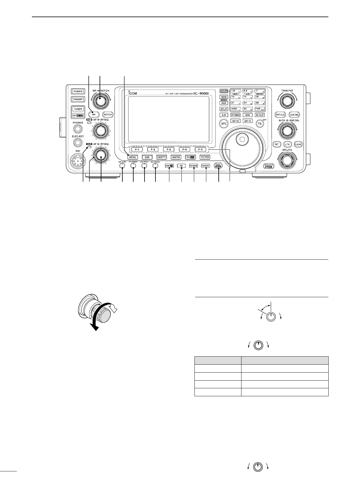
■ Front panel (continued)
3
1
PANEL DESCRIPTION
!6 !8!7
!4
!5
!9 @0 @1 @2 @3 @4 @5 @6 @7 @8
!38
 Loading...