■ Optional external tuner operation
• AH-4 HF AUTOMATIC ANTENNA TUNER
The AH-4 matches the IC-7600 to a long wire an-
tenna more than 7 m/23 ft long (3.5 MHz and above).
• See
p. ?? for the transceiver and AH-4 connection.
• See the AH-4 instruction manual for AH-4 installa-
tion and antenna connection details.
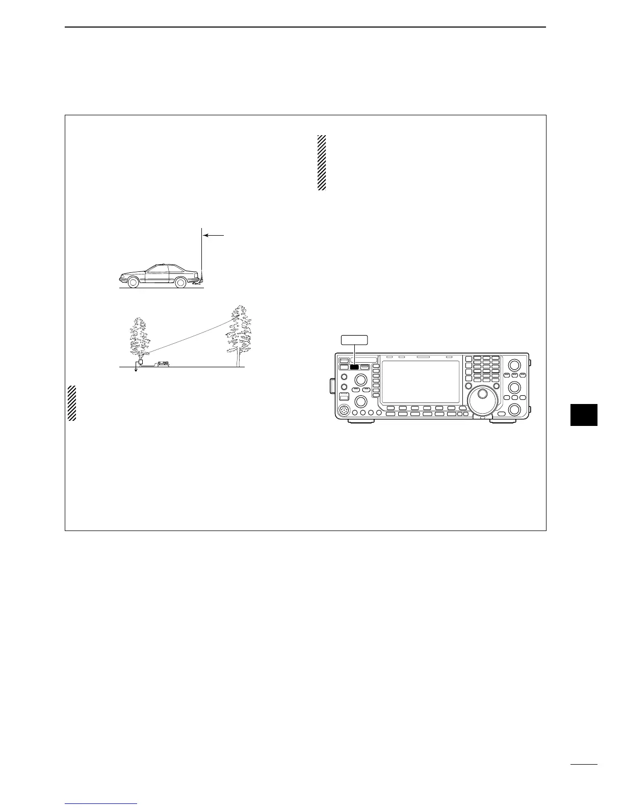
AH-4 setting example:
For mobile operation
For outdoor operation
Long wire
Optional AH-2b
antenna element
R DANGER: HIGH VOLTAGE!
NEVER touch the antenna element while tuning
or transmitting.
NEVER operate the AH-4 without an antenna wire.
The tuner and transceiver will be damaged.
NEVER operate the AH-4 when it is not grounded.
Transmitting before tuning may damage the trans-
ceiver. Note that the AH-4 cannot tune when using a
½λ long wire or multiple of the operating frequency.
When connecting the AH-4, the antenna connec-
tor assignments are [ANT2] for the internal tuner
and [ANT1] for the AH-4. The antenna indicator in
the LCD displays “ANT1(EXT)” when the AH-4 is
connected and selected.
• AH-4 operation
Tuning is required for each frequency. Be sure to
re-tune the antenna before transmitting when you
change the frequency— even slightly.
q Set the desired frequency in an HF or 50 MHz
band for use with the AH-4.
• The AH-4 will not operate on frequencies outside
of ham bands.
w Push [TUNER] for 1 sec.
• The indicator on the switch blinks while tuning.
TUNER
e The indicator on the switch lights constantly when
tuning is complete.
• When the connected wire cannot be tuned, the
indicator on the switch goes out and the AH-4 is
bypassed. At that point the antenna wire connec-
tion is to the transceiver directly, and not via the
AH-4 antenna tuner.
r To bypass the AH-4 manually, push [TUNER].
M If the tuner cannot tune the antenna
Check the following and try again:
• the [ANT] connector selection.
• the antenna connection and feedline.
• the untuned antenna SWR. (Less than 3:1 for HF
bands; Less than 2.5:1 for 50 MHz band)
• the transmit power. (8 W for HF bands; 15 W for
50 MHz band)
• the power source voltage/capacity.
If the tuner cannot reduce the SWR to less than 1.5:1
after checking the above, perform the following:
• repeat manual tuning several times.
• tune with a 50 Ω dummy load and re-tune the an-
tenna.
• turn power OFF and ON.
• adjust the antenna feedline length. (This is effective
for higher frequencies in some cases.)
M Tuning a narrow bandwidth antenna
Some antennas, especially for the low bands, have a
narrow bandwidth. These antennas may not be tuned
beyond the edge of their operating bandwidth, there-
fore, tune such an antenna as follows:
[Example]: Suppose you have an antenna which
has an SWR of 1.5:1 at 3.55 MHz and an
SWR of 3:1 at 3.8 MHz.
q Push [TUNER] to turn the antenna tuner ON.
w Select CW mode.
e Turn OFF the break-in function. (p. ??)
r
Push [TRANSMIT] to set to the transmit condition.
t Set 3.55 MHz and key down.
y Set 3.80 MHz and key down.
u
Push [TRANSMIT] to return to the receive condition.
114
8
ANTENNA TUNER OPERATION
1
2
3
4
5
6
7
8
9
10
11
12
13
14
15
16
17
18
19
20
21

 Loading...


