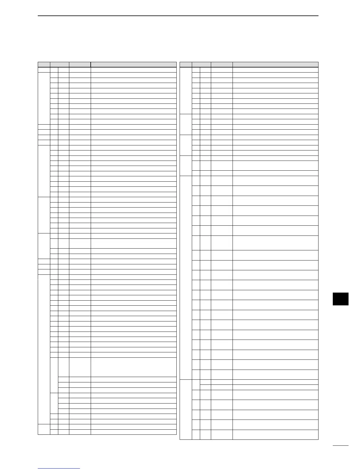
D Command table
151
12
CONTROL COMMAND
1
2
3
4
5
6
7
8
9
10
11
12
13
14
15
16
17
18
19
20
21
Cmd.
Sub cmd.
Data Description
00 see p. 000 Send frequency data (transceive)
01 00 Select LSB (transceive)
01 Select USB (transceive)
02 Select AM (transceive)
03 Select CW (transceive)
04 Select RTTY (transceive)
05 Select FM (transceive)
07 Select CW-R (transceive)
08 Select RTTY-R (transceive)
12 Select PSK (transceive)
13 Select PSK-R (transceive)
02 see p. 000 Read band edge frequencies
03 see p. 000 Read operating frequency
04 see p. 000 Read operating mode
05 see p. 000 Set operating frequency
06 00 Select LSB
01 Select USB
02 Select AM
03 Select CW
04 Select RTTY
05 Select FM
07 Select CW-R
08 Select RTTY-R
12 Select PSK
13 Select PSK-R
07 Select VFO mode
B0 Exchange main and sub bands
B1 Equalize main and sub bands
C0 Turn the dualwatch OFF
C1 Turn the dualwatch ON
D0 Select main band
D1 Select sub band
08 Select memory mode
0001 to
0099
Select memory channel
(0001=M-CH01, 0099=M-CH99)
0100 Select program scan edge channel P1
0101 Select program scan edge channel P2
09 Memory write
0A Copying memory contents into VFO
0B Memory clear
0E 00 Scan stop
01 Programmed/memory scan start
02 Programmed scan start
03
:F scan start
12 Fine programmed scan start
13 Fine
:F scan start
22 Memory scan start
23 Select memory scan start
A1 Select
:F scan span ±5 kHz
A2 Select
:F scan span ±10 kHz
A3 Select
:F scan span ±20 kHz
A4 Select
:F scan span ±50 kHz
A5 Select
:F scan span ±100 kHz
A6 Select
:F scan span ±500 kHz
A7 Select
:F scan span ±1 MHz
B0 Set as non-select channel
B1 Set as select channel
( The previously set number by CI-V is set after
turning power ON, or “1” is selected if no selec
-
tion is performed.)
01
Set as select channel “(1”
02
Set as select channel “(2”
03
Set as select channel “(3”
B2 00 Set “ALL” for select memory scan
01
Set “(1” for select memory scan
02
Set “
(2” for select memory scan
03
Set “(3” for select memory scan
D0 Set scan resume OFF
D3 Set scan resume ON
0F 00 Turn the split function OFF
01 Turn the split function ON
Cmd.
Sub cmd.
Data Description
10 00 Select 10 Hz (1 Hz) tuning step
01 Select 100 Hz tuning step
02 Select 1 kHz tuning step
03 Select 5 kHz tuning step
04 Select 9 kHz tuning step
05 Select 10 kHz tuning step
06 Select 12.5 kHz tuning step
07 Select 20 kHz tuning step
08 Select 25 kHz tuning step
11 00 Send/read attenuator OFF
06 Send/read 6 dB attenuator
12 Send/read 12 dB attenuator
18 Send/read 18 dB attenuator
12 0000 Send/read ANT1 selection (RX ANT OFF)
0001 Send/read ANT1 selection (RX ANT ON)
0100 Send/read ANT2 selection (RX ANT OFF)
0101 Send/read ANT2 selection (RX ANT ON)
13 00 Announce all data with voice synthesizer
01 Announce frequency and S-meter level with
voice synthesizer
02
Announce receive mode with voice synthesizer
14 01 0000 to
0255
Send/read [AF] level
(0000=max. CCW, 0255=max. CW)
02 0000 to
0255
Send/read [RF] level
(0000=max. CCW, 0255=11 o'clock)
03 0000 to
0255
Send/read [SQL] level
(0000=11 o'clock, 0255=max. CW)
06 0000 to
0255
Send/read [NR] level
(0000=0%, 0255=100%)
07 0000 to
0255
Send/read inner [TWIN PBT] position
(0000=max. CCW, 0128=center, 0255=max. CW)
08 0000 to
0255
Send/read outer [TWIN PBT] position
(0000=max. CCW, 0128=center, 0255=max. CW)
09 0000 to
0255
Send/read CW pitch
( 0000=300 Hz, 0128=600 Hz, 0255=900 Hz;
5 Hz steps)
0A 0000 to
0255
Send/read [RF POWER] level
(0000=max. CCW, 0255=max. CW)
0B 0000 to
0255
Send/read [MIC GAIN] level
(0000=max. CCW, 0255=max. CW)
0C 0000 to
0255
Send/read [KEY SPEED] level
(0000=max. CCW, 0255=max. CW)
0D 0000 to
0255
Send/read [NOTCH] position
(0000=max. CCW, 0128=center, 0255=max. CW)
0E 0000 to
0255
Send/read COMP level
(0000=0, 0255=10)
0F 0000 to
0255
Send/read [BK-IN DELAY] position
(0000=max. CCW, 0255=max. CW)
10 0000 to
0255
Send/read [BAL] position
(0000=max. CCW, 0128=center, 0255=max. CW)
12 0000 to
0255
Send/read NB level
(0000=0%, 0255=100%)
14 0000 to
0255
Send/read DRIVE gain
(0000=0%, 0255=100%)
15 0000 to
0255
Send/read Monitor gain
(0000=0%, 0255=100%)
16 0000 to
0255
Send/read VOX gain
(0000=0%, 0255=100%)
17 0000 to
0255
Send/read Anti VOX gain
(0000=0%, 0255=100%)
19 0000 to
0255
Send/read BRIGHT level
(0000=0%, 0255=100%)
15 01 00 Read squelch condition (squelch close)
01 Read squelch condition (squelch open)
02 0000 to
0255
Read S-meter level
(0000=S0, 0120=S9, 0241=S9+60)
11 0000 to
0255
Read RF power meter
(0000=0, 0143=50, 0213=100)
12 0000 to
0255
Read SWR meter
(0000=SWR1.0, 0048=SWR1.5, 0080=SWR2.0)
13 0000 to
0255
Read ALC meter
(0000=0, 0120=Max.)
14 0000 to
0255
Read COMP meter
(0000=0, 0130=15, 0241=30)

 Loading...


