95
14
CONTROL COMMAND
2001 NEW 2001 NEW
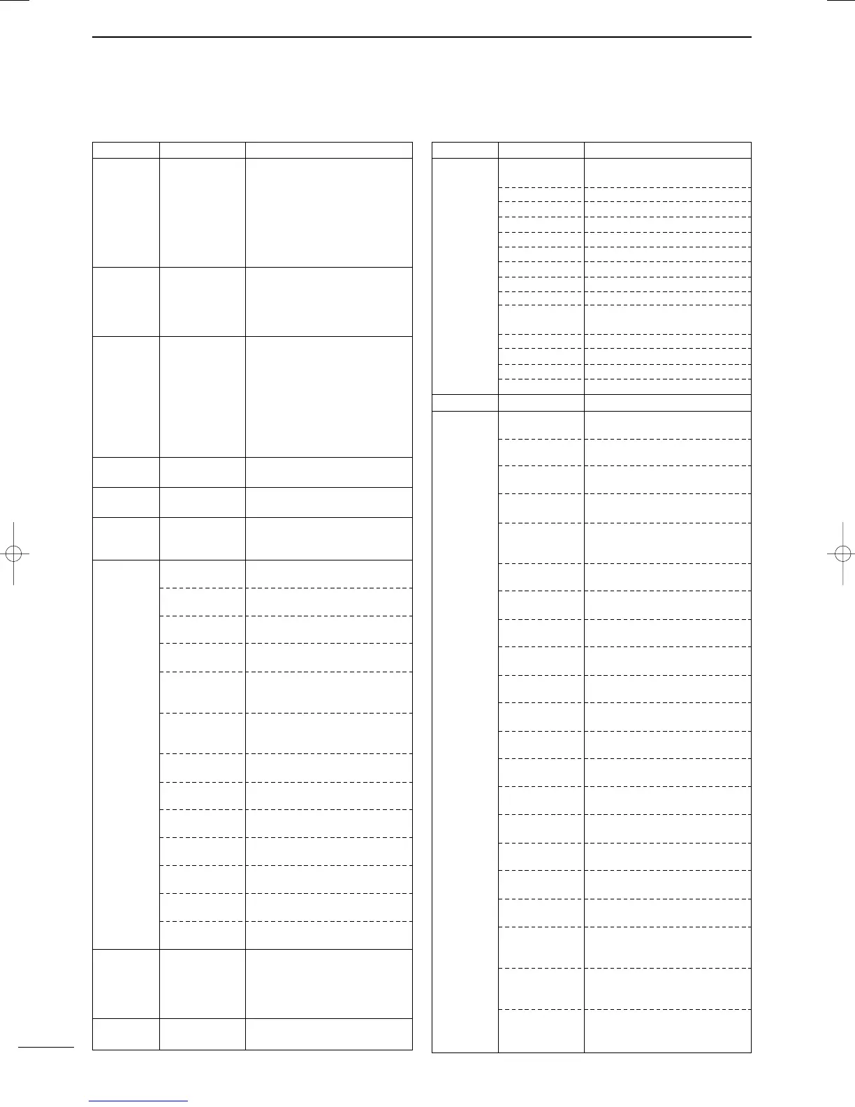
• Command table (continued)
Command Sub command Description
0E A1–A7 Set ∂F scan span (A1=±5 kHz,
A2=±10 kHz, A3=±20 kHz,
A4=±50 kHz, A5=±100 kHz,
A6=±500 kHz, A7=±1 MHz)
B0 Set as non-select channel
B1 Set as select channel
D0 Set scan resume OFF
D3 Set scan resume ON
0F 00 Turn the split function OFF
01 Turn the split function ON
10 Select simplex operation
11 Select –DUP operation
12 Select +DUP operation
10 00 Select 10 Hz (1 Hz) tuning step
01 Select 100 Hz tuning step
02 Select 1 kHz tuning step
03 Select 5 kHz tuning step
04 Select 9 kHz tuning step
05 Select 10 kHz tuning step
06 Select 12.5 kHz tuning step
07 Select 20 kHz tuning step
08 Select 25 kHz tuning step
11 — Select/read attenuator (0=OFF,
1=ON)
12 — Select/read antenna selection
(0=ANT1, 1=ANT2)
13 00 Announce with voice synthesizer
01 (00=all data; 01=frequency and
02 S-meter level; 02=receive mode)
14 01 + Level data [AF] level setting (0=max. CCW to
255=max. CW)
02 + Level data [RF] level setting (0=max. CCW to
255=11 o’clock)
03 + Level data [SQL] level setting (0=11 o’clock to
255=max. CW)
06 + Level data [NR] level setting (0=min. to
255=max.)
07 + Level data Inside [TWIN PBT] setting or IF
shift setting (0=max. CCW,
128=center, 255=max. CW)
08 + Level data Outside [TWIN PBT] setting
(0=max. CCW, 128=center,
255=max. CW)
09 + Level data [CW PITCH] setting (0=300 Hz,
128=600 Hz, 255=900 Hz)
0A + Level data [RF PWR] setting (0=mini. to
255=max.)
0B + Level data [MIC GAIN] setting (0=mini. to
255=max.)
0C + Level data [KEY SPEED] setting (0=slow to
255=fast)
0D + Level data [NOTCH] setting (0=low freq. to
255=high freq.)
0E + Level data COMP Level Delay setting (0=0 to
10=10)
0F + Level data Break-IN DELAY setting (20=2.0d
to 130=13.0d)
15 01 Read squelch condition
02 Read S-meter level
11 Read RF power meter
12 Read SWR meter
13 Read ALC meter
16 02 Preamp (0=OFF; 1=preamp 1;
2=preamp 2)
Command Sub command Description
16 12 AGC selection (0=OFF; 1=Slow;
2=Mid; 3=Fast)
22 Noise blanker (0=OFF; 1=ON)
40 Noise reduction (0=OFF; 1=ON)
41 Auto notch (0=OFF; 1=ON)
42 Repeater tone (0=OFF; 1=ON)
43 Tone squelch (0=OFF; 1=ON)
44
Speech compressor (0=OFF; 1=ON)
45 Monitor (0=OFF; 1=ON)
46 VOX function (0=OFF; 1=ON)
47 Break-in (0=OFF; 1=semi break-
in; 2=full break-in)
48 Manual notch (0=OFF; 1=ON)
49 RTTY filter (0=OFF; 1=ON)
4B DTCS (0=OFF; 1=ON)
4C VSC (0=OFF; 1=ON)
19 00 Read the transceiver ID
1A 00 Send/read memory contents (see
p. 97 for details)
01 Send/read band stacking register
contents (see p. 97 for details)
02 Send/read memory keyer con-
tents (see p. 97 for details)
03 Send/read the selected filter width
(0=50 Hz to 40/31=3600/2700 Hz)
04 Send/read the selected AGC time
constant (0=OFF, 1=0.1/0.3 sec. to
13=6.0/8.0 sec.)
0501 Send/read LCD contrast (0=0% to
255=100%)
0502 Send/read LCD backlight (0=0% to
255=100%)
0503 Send/read beep gain (0=min. to
255=max.)
0504 Send/read beep gain limit (0=OFF,
1=ON)
0505 Send/read calibration marker
(0=OFF, 1=ON)
0506 Send/read confirmation beep
(0=OFF, 1=ON)
0507 Send/read band edge beep
(0=OFF, 1=ON)
0508 Send/read RF/SQL control set
(0=Auto, 1=SQL, 2=RF+SQL)
0509 Send/read meter peak hold set
(0=OFF, 1=ON)
0510 Send/read COMP meter set
(0=OFF, 1=ON)
0511 Send/read quick split set (0=OFF,
1=ON)
0512 Send/read split offset –9.999 to
+9.999 MHz (see p. 98 for details)
0513 Send/read split lock set (0=OFF,
1=ON)
0514 Send/read duplex offset 0.000 to
9.999 MHz for HF (see p. 98 for
details)
0515 Send/read duplex offset 0.000 to
9.999 MHz for 50 MHz band (see
p. 98 for details)
0516 Send/read duplex offset 0.000 to
9.999 MHz for 144 MHz band
(see p. 98 for details)
IC-7400.qxd 02.4.2 11:36 Page 95