5: S
PECIAL
F
UNCTIONS
5-26 S
MART
AXIS P
RO
/L
ITE
U
SER
'
S
M
ANUAL
FT9Y-B1378
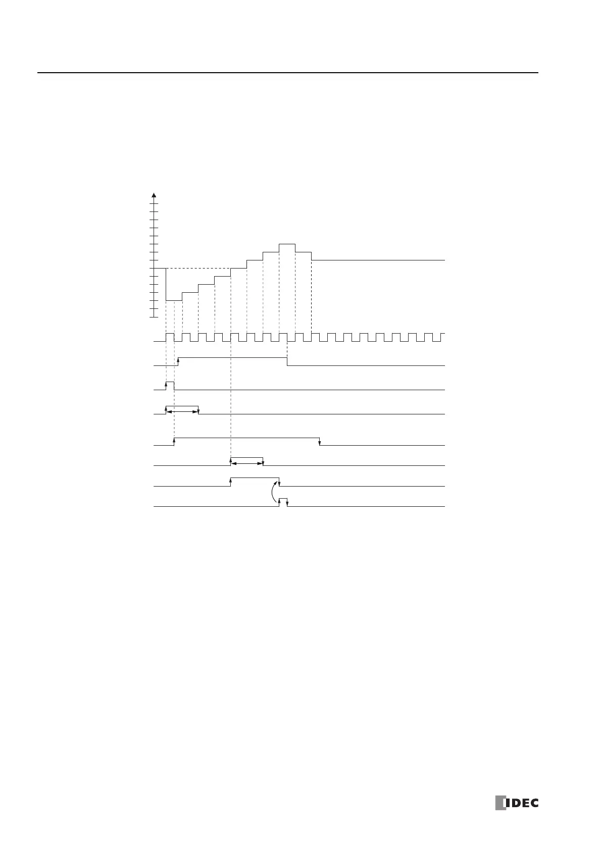
Timing chart 1
Single-phase high-speed counter (group 1) timing chart
Operating conditions
The counting mode is set to Up/down selection reversible counter and reset input (I2) is used.
One preset value is used, and when the values match, output Q1 turns on and the current value is kept.
Overflow and underflow are not used.
1. When reset input (I2) turns on, the reset value (D8054, D8055) is stored in the current value (D8050, D8051).
In this situation, reset status (M8033) turns on for only one scan.
2. When gate input (M8031) turns on, the counting begins.
3. The counting direction (count up/count down) is determined by the on/off state of the up/down selection input (I1), and the
pulse input (I0) is counted. The current value is updated with each scan.
4. When the current value and preset value 1 (D8052, D8053) match, the preset value 1 comparison output (Q1) and Comparison
ON status (M8034) turn on. When the Keep check box is selected in the settings in the WindLDR High-speed Counter
Settings, the current value is kept.
5. Q1 maintains the on state until comparison output reset (M8030) turns on. M8034 turns on for only one scan.
6. When the gate output turns off, counting stops.
Note: High-speed counter usage precautions
The high-speed counter starts the count operation with the following two conditions:
• The SmartAXIS starts operation
• The gate input is turned on
To start the count operation, turn the gate input on from off while the SmartAXIS is running. When the gate input is already on and the SmartAXIS
is stopped, the count operation starts when the SmartAXIS is switched from stop to run.
When a user program is downloaded during the count operation, the count operation stops. The count operation will restart by setting the
SmartAXIS to run.
Current value
Preset value 1=6
Up count
One scan
Pulse input I0
I1
Q1
I2
M8033
M8031
M8030
M8034
(D8554,D8555)
Up/down selection
input
Gate input
Preset value
Comparison ON status
Reset status
Reset input
Down count
One scan
Comparison output
reset
Preset value 1
Comparison output
14
13
12
11
10
9
8
7
6
5
4
3
2
1
0
Reset value=2
Reset