S
MART
AXIS P
RO
/L
ITE
U
SER
'
S
M
ANUAL
FT9Y-B1378 5-25
5: S
PECIAL
F
UNCTIONS
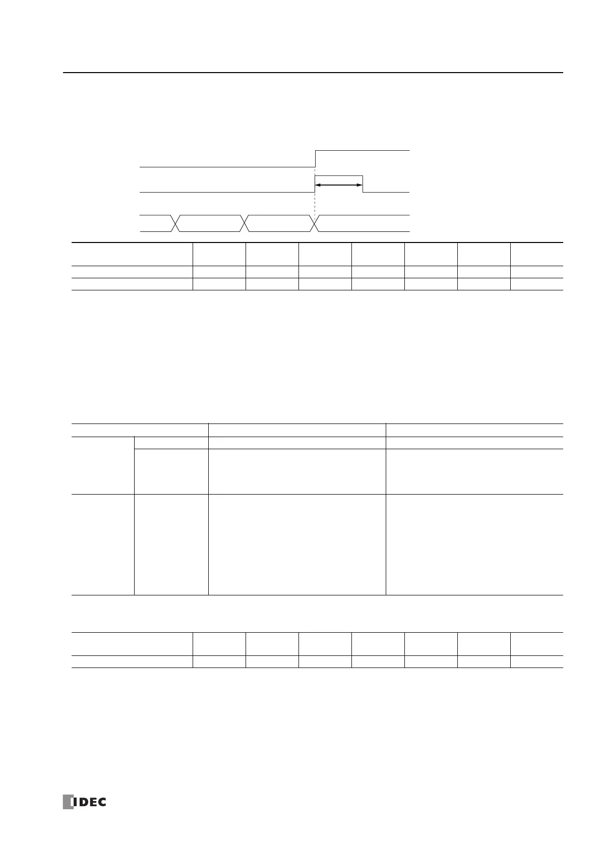
• HSC reset input and reset status
When the HSC reset input is enabled in group 1 or group 3, turn on HSC reset input I2 or I5 to return the current value to the reset
value.
In this situation, reset status turns on for only one scan.
To use the reset input with the group 1 or group 3 single-phase high-speed counter, use I2 (group 2) or I5 (group 4). When not
using I2 or I5 as a reset input, they can be used as normal input, high-speed counters, catch input, interrupt input, or frequency
measurements.
• Count direction flag
These special internal relays maintain whether the group 1 or group 3 current value count is the adding direction or the subtracting
direction. When these special internal relays are on, they indicate the adding direction. When they are off, they indicate the
subtracting direction.
The flag operates as follows for each counting mode setting.
*1 When operating as a two-phase high-speed counter, the count direction flag does not reflect the current adding/subtracting direction and
indicates the adding/subtracting direction for the previous comparison.
Group
1
(I0 to I1)
2
(I2)
3
(I3 to I4)
4
(I5)
5
(I6)
6
(I7)
Read/Write
HSC Reset Input I2—I5————
Reset Status M8033 — M8050 — — — R
Counting mode
Count direction flag status When the count direction flag changes
Single-phase
high-speed
counter
Adding counter • Always the adding direction • None
Up/down
selection
reversible
counter
• Adding direction when the up/down selection
input is on.
• Subtracting direction when the up/down
selection input is off.
• When the up/down selection input status has
changed.
Two-phase
high-speed
counter
2-edge count /
4-edge count
• Adding direction if the current value is
incremented and reached to the preset value
or the current value overflows in the previous
comparison operation.
• Subtracting direction if the current value is
decremented and reached to the preset value
or the current value underflows in the previous
comparison operation.
*1
• The default is the adding direction.
• When the current value and the preset value
are equal.
• When a current value overflow or underflow
has occurred.
Group
1
(I0 to I1)
2
(I2)
3
(I3 to I4)
4
(I5)
5
(I6)
6
(I7)
Read/Write
Count Direction flag M8037 — M8054 — — — R
HSC reset input
Reset status
NN-1 N+1
Reset value (initial value)Current value
One scan