S
MART
AXIS P
RO
/L
ITE
U
SER
'
S
M
ANUAL
FT9Y-B1378 10-27
10: U
SER
C
OMMUNICATION
I
NSTRUCTIONS
Configuring Barcode Reader
The values shown below are an example of configuring a barcode reader. For actual settings, see the user’s manual for the
barcode reader.
Device Addresses
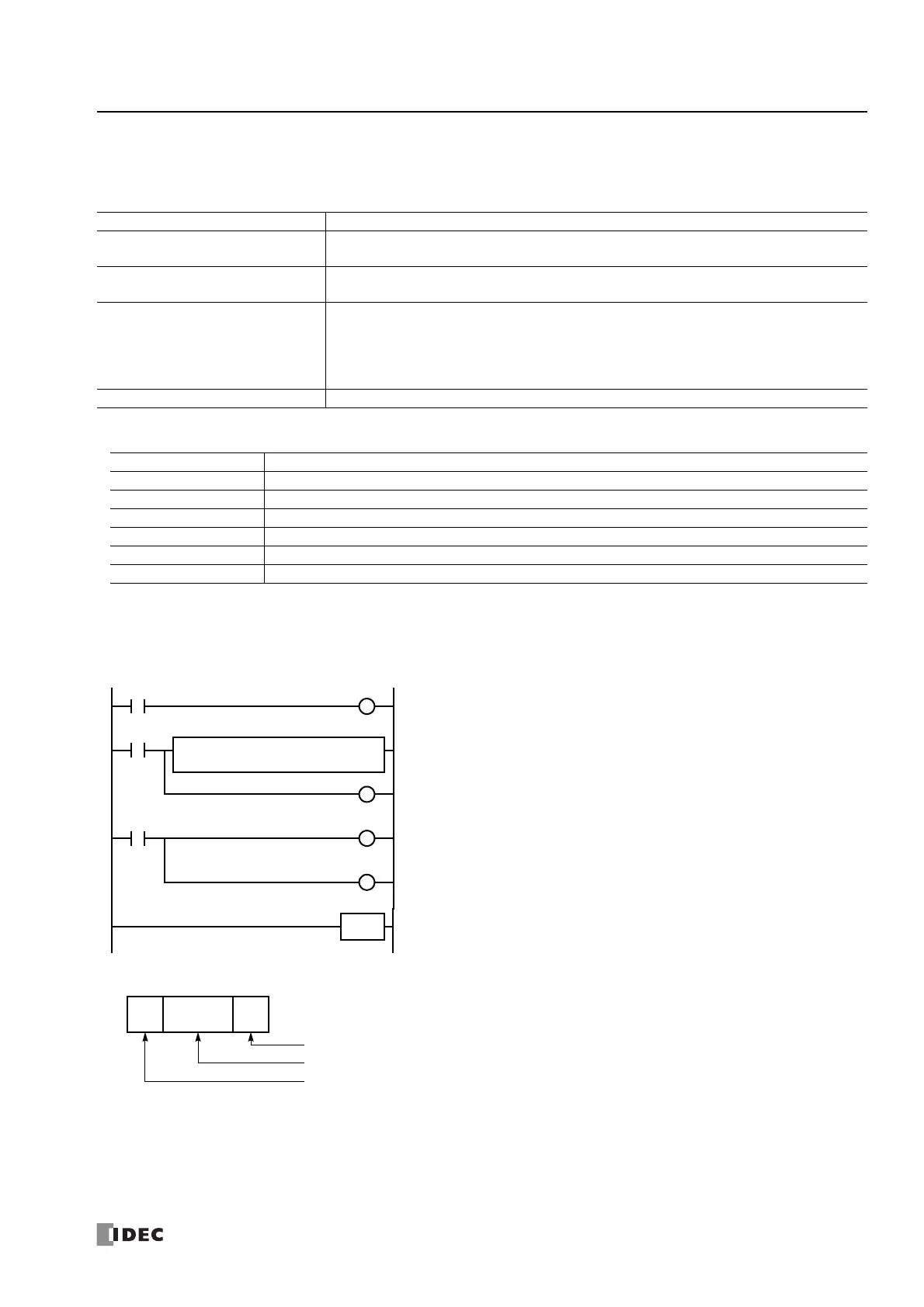
Ladder Diagram
When the SmartAXIS starts operation, the RXD2 instruction is executed to wait for incoming data. When data receive is complete,
the data is stored to data registers D20 and D21. The receive completion signal is used to execute the RXD2 instruction to wait for
another incoming data.
RXD2 Data
Synchronization mode Auto
Read mode
Single read or
multiple read
Communication parameter
Baud rate:
Parity check:
9600bps
Even
Data bits:
Stop bit:
7
1
Other communication settings
Header:
Data echo back:
Output timing:
Data output filter:
Sub serial:
02h
No
Output priority 1
No
No
Terminator:
BCR data output:
Character suppress:
Main serial input:
03h
Yes
No
No
Comparison preset mode Not used
M100 Input to start receiving barcode data
M101 Receive completion output for barcode data
M8120 Initialize pulse special internal relay
D20 Store barcode data (upper 4 digits)
D21 Store barcode data (lower 4 digits)
D100 Receive status data register for barcode data
D101 Receive data byte count data register
M8120
END
S1
10
D2
D100
D1
M101
M101
RXD
2
M100
M100
S
M100
R
M101
R
M100
S
M8120 is the initialize pulse special internal relay used to set M100.
At the rising edge of M100, RXD2 is executed to be ready for receiving data.
Even after M100 is reset, RXD2 still waits for incoming data.
When data receive is complete, M101 is turned on, then M100 is set to execute RXD2 to
receive the next incoming data.
STX
(02h)
ETX
(03h)
Data Register
D20B42
End Delimiter
D20, ASCII to BCD Conversion (4 digits), Repeat: 2
Start Delimiter