S
MART
AXIS P
RO
/L
ITE
U
SER
'
S
M
ANUAL
FT9Y-B1378 2-7
2: P
RODUCT
S
PECIFICATIONS
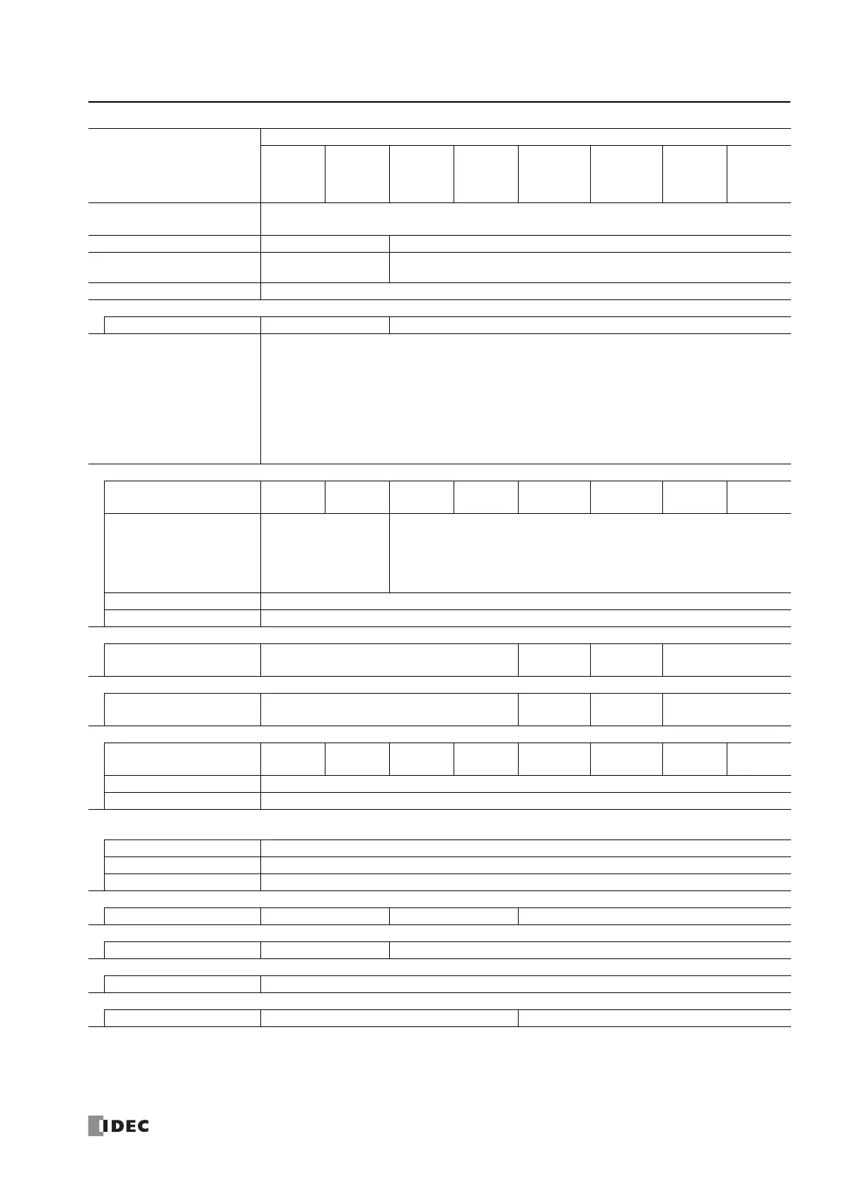
Note1: 1 step is equivalent to 4 bytes.
Note2: When FBD program is selected as the programming language.
Note3: Among data registers D0 to D1999, only D0 to D999 are backed up.
Note4: Set the calendar/clock using WindLDR to use the clock function.
Data Register
12-I/O type: 400
24-I/O type, 40-I/O type, 48-I/O type: 2,000
Counter (adding, reversible) 100 200
Timer (1-sec, 100ms,
10ms, 1ms)
100 200
Input Filter Without filter, 3 to 15ms (selectable in increments of 1ms)
Catch Input/Interrupt Input
Input Points 46
Self-diagnostic Function
Keep data
Power failure
Clock error
Watchdog timer
Timer/counter preset value change error
User program syntax
User program execution
System error
Memory cartridge transfer error
High-speed Counter
Points
Total
4 points
—
Total
6 points
—
Total
6 points
—
Total
6 points
—
Maximum Counter
Frequency
Single/two-phase
selectable: 100kHz
(2 points)
Single-phase: 100kHz
(2 points)
Single/two-phase selectable: 100kHz (2 points)
Single-phase: 100kHz (4 points)
Counting Range 0 to 4,294,967,295 (32 bits)
Operation Mode Rotary encoder mode and adding counter mode
Pulse Output (Maximum frequency: 100kHz)
Points —
2
(Q14, Q15)
—
2
(Q14, Q15)
Pulse Output (Maximum frequency: 5kHz)
Points —
2
(Q16, Q17)
—
2
(Q16, Q17)
Analog Voltage Input
Points (Terminal No.) 2 (I6, I7) —
4
(I14 to I17)
—
6
(I22 to I27)
—
8 (I26, I27,
I30 to I35)
—
Input voltage Range 0 to 10V DC
Digital Resolution 0 to 1000
USB
Port
Points 1
USB Standard USB 2.0
Connector Mini-B type
Expansion Communication Ports
Points —1 2
Ethernet Port
Points —1
Memory Cartridge Connectors
Points 1
SD Memory Card Slots
Points —1
Type Number
FT1A-
H12RA
B12RA
H12RC
B12RC
H24RA
B24RA
H24RC
B24RC
H40RKA
H40RSA
B40RKA
B40RSA
H40RC
B40RC
H48KA
H48SA
B48KA
B48SA
H48KC
H48SC
B48KC
B48SC