S
MART
AXIS P
RO
/L
ITE
U
SER
'
S
M
ANUAL
FT9Y-B1378 12-9
12: R
EMOTE
I/O
Remote I/O Slave HMI Function
This section describes the menu screen when the SmartAXIS Pro is configured as a remote I/O slave.
For the button operations on the menu screen, see Chapter 6 "HMI Function".
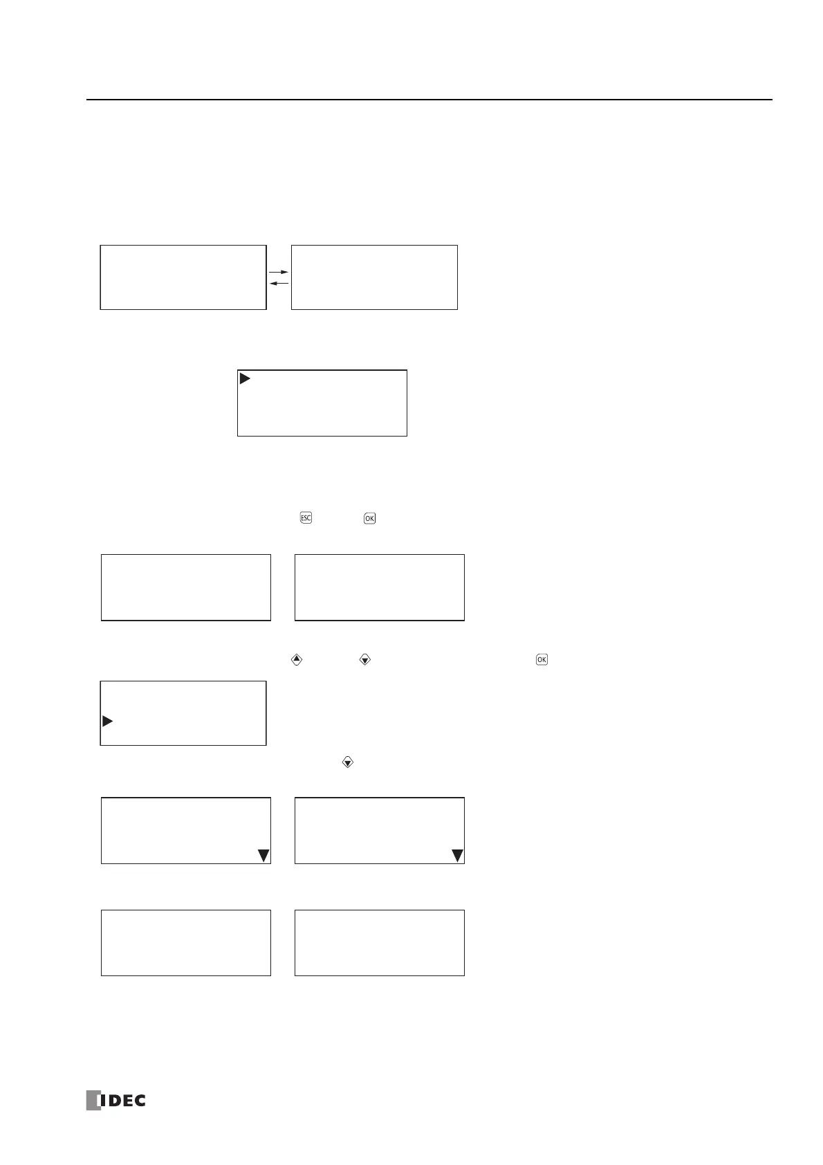
Standard Screen
This screen displays content according to the communication state with the remote I/O master.
System menu
The menu items displayed when the SmartAXIS is configured as a remote I/O slave.
*1 The remote I/O slave device monitor is read-only. The device values cannot be modified.
Monitoring the Remote I/O Slave Status
You can check the system software version and the communication cycle of the remote I/O slave.
1. On the standard screen, press the (ESC) + (OK) buttons.
The system menu is displayed.
2. Select Status Monitor with the (up) and (down) buttons and press the (OK) button.
3. The system version is displayed. Press the (down) button.
The communication cycle is displayed.
• Configurations
• Device Monitor
*1
• Status Monitor
• Error Status
Current: The current communication cycle with the remote I/O master.
Maximum: The maximum communication cycle from when the connection with the remote I/O master was
established until the present.
Minimum: The minimum communication cycle from when the connection with the remote I/O master was
established until the present.
Remote I/O Slave
Connected
Remote I/O Slave
Disconnected
Configurations
Device Monitor
Status Monitor
Error Status
Remote I/O Slave
Connected
Remote I/O Slave
Disconnected
Configurations
Device Monitor
Status Monitor
Error Status
System Version:
ࠉ
2.00
Communication state:
ࠉ
Connected
System Version:
ࠉ
2.00
Communication state:
ࠉ
Disconnected
Communication cycle
㸸
Current:
Maximum:
Minimum:
PV
PV
PV
Communication cycle
㸸
Current:
Maximum:
Minimum:
PV
PV
PV