3: I
NSTALLATION
AND
W
IRING
3-10 S
MART
AXIS P
RO
/L
ITE
U
SER
'
S
M
ANUAL
FT9Y-B1378
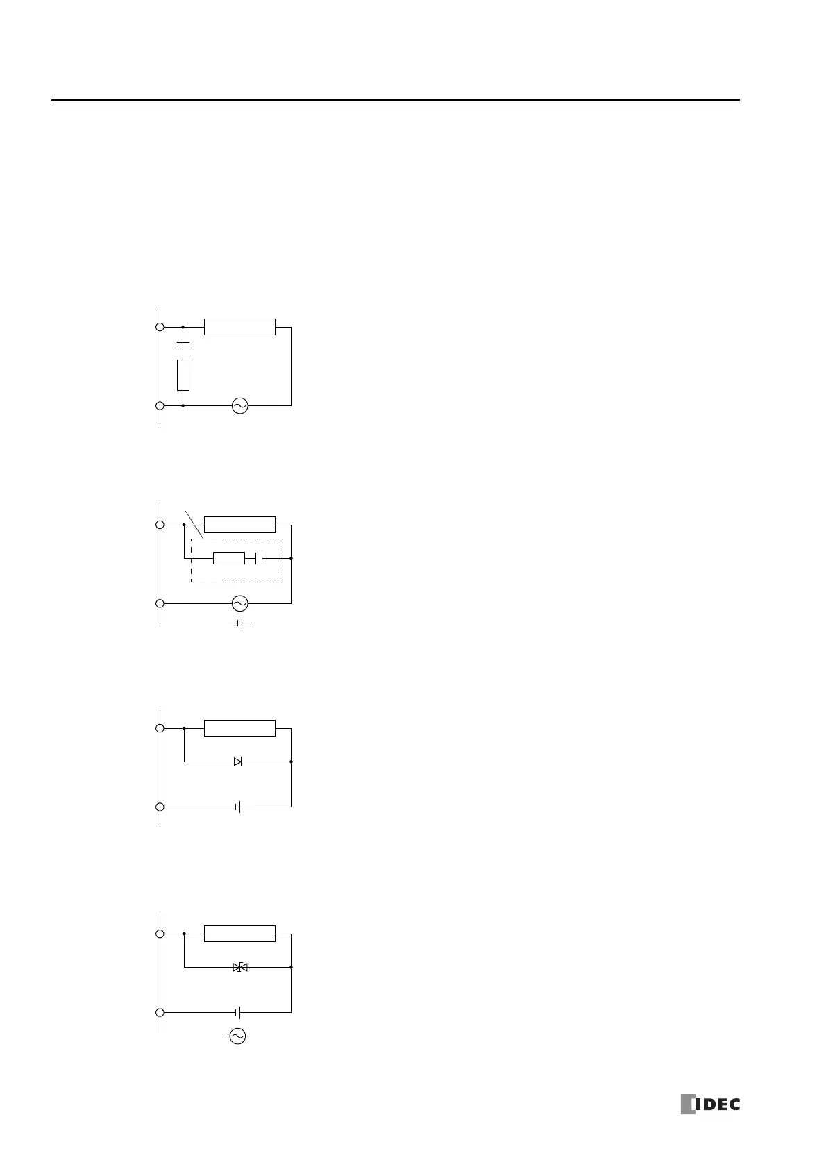
Output Protection Circuit
When a motor, solenoid, or similar inductive load is connected, the life of the contact is shortened due to the inrush current and
counter-electromotive force acting on the load. Set up a protection circuit to prevent this from happening. Choose a protection
circuit from A through D shown below, according to the power supply, and connect the protection circuit to the outside of the
SmartAXIS.
For protection of the transistor output of the SmartAXIS modules, connect protection circuit C shown below to the transistor output
circuit.
Protection Circuit A
Protection Circuit B
Protection Circuit C
Protection Circuit D
Inductive Load
COM
C
R
Output Q
This protection circuit can be used when the load impedance is smaller
than the RC impedance in an AC load power circuit.
R: Resistor of approximately the same resistance value as the load
C: 0.1 to 1 µF
Inductive Load
COM
R
Output Q
C
+
or
–
Surge Killer
This protection circuit can be used for both AC and DC load power
circuits.
R: Resistor of approximately the same resistance value as the load
C: 0.1 to 1 µF
Inductive Load
COM
Output Q
+–
Diode
This protection circuit can be used for DC load power circuits.
Use a diode with the following ratings.
Reverse withstand voltage: Power voltage of the load circuit × 10
Forward current:More than the load current
Inductive Load
COM
Output Q
+
or
–
Varistor
This protection circuit can be used for both AC and DC load power
circuits.