S
MART
AXIS P
RO
/L
ITE
U
SER
'
S
M
ANUAL
FT9Y-B1378 4-13
4: O
PERATION
B
ASICS
For FBD Program
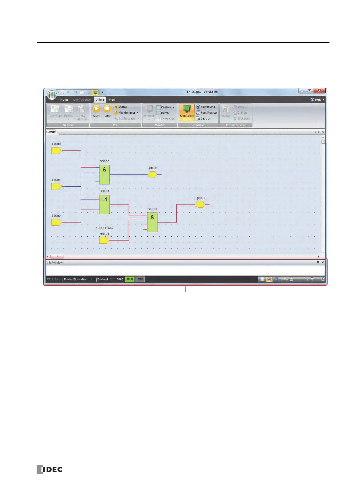
1. From the WindLDR menu bar, select Online > Simulation > Simulation.
2. Double-click the input FB to change the state.
• When you turn on both input I0 and input I1, output Q0 turns on.
• When you turn on either input I1 or input I2, output Q1 continues to turn on and off in a one second cycle.
Notes:
• To quit the simulation, select Online > Simulation > Simulation again.
• You can check the state of the input connectors and output connectors of each FB. When input connectors, output connectors, and
connection lines are in red, they are on. Blue indicates off.
• For details on the state of unconnected input connectors of the FBs, see the " SmartAXIS FBD Programming Manual".