EasyManuals Logo

IDS X64 User Manual

IDS X64
44 pages
To Next Page IconTo Next Page
To Previous Page IconTo Previous Page
Page #12 background imageLoading...
Page #12 background image
Section: 3
IDS X64 User Manual 700-398-01D Issued August 2010
12
3.1
Viewing Data on an LED Keypad
3.1.1
LED Status Indicators
Table 1 shows the LED status indicators and the meaning of their various states.
Table 1: LED Indicators
ARM LED
(red)
READY LED
(green)
POWER LED
(red)
AWAY LED
(red)
ZONE LED
(amber)
Ready to be
Ready for
(Check Alarm
Memory zone
details
BEFORE re-
= on = off =flashing
3.1.2
Numerical Values
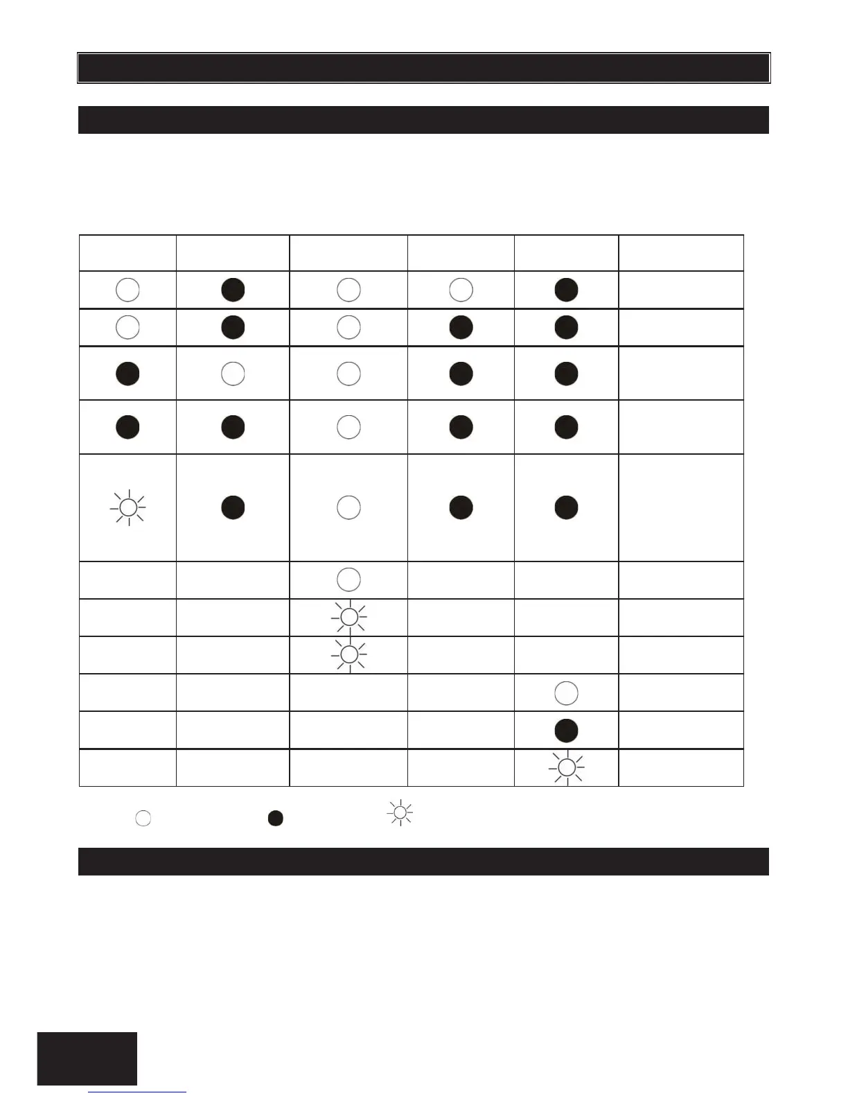
Simple numerical values are represented via the zone LEDs. For instance, if zone LED 15 is on, it is
representing a value of 15. This is commonly used when enabling and disabling bitmapped locations.
Each zone LED directly corresponds to a number of the same value. For numbers or information that
exceeds a value of 16, binary-coded decimal values are used, as explained in the following sections.

Table of Contents

Other manuals for IDS X64

Questions and Answers:

Question and Answer IconNeed help?

Do you have a question about the IDS X64 and is the answer not in the manual?

IDS X64 Specifications

General IconGeneral
Keypads8
Stay/Away ArmingYes
Tamper ProtectionYes
Operating SystemProprietary
Supported ProtocolsContact ID, SIA
Power Supply16.5VAC
Backup Battery12VDC 7Ah
AlertsSMS
RAMUnknown

Related product manuals