p.31OUTPUT WIRING
8 INPUT WIRING
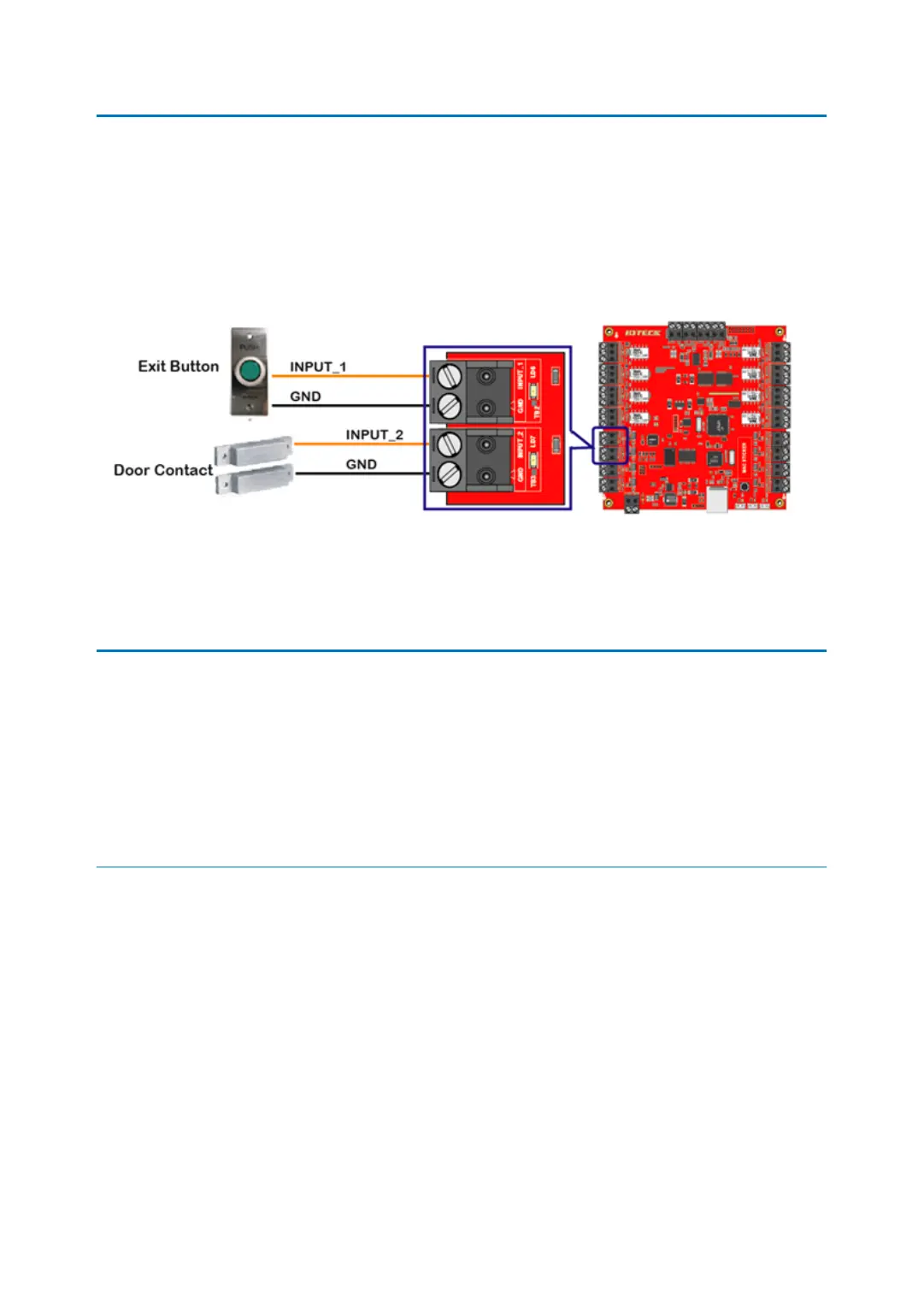
Connect Door contact and exit button to Input Port terminal block (INPUT_1 ~ INTPUT_8) of
iMDC-RIM as follow.
●
Connect Exit Button to Input Port terminal block (INPUT_1) of iMDC-RIM.
●
Connect Door Contact to Input Port terminal block (INPUT_2) of iMDC-RIM.
9 OUTPUT WIRING
Connect Door Lock and Alarm Device to Output Port terminal block (Relay outputs) of iMDC
-RIM as follow.
9.1 DOOR LOCK WIRING
IN CASE OF POWER FAIL SAFE DOOR LOCK;
●
Connect +12V wire of DC12V power supply to Output Port terminal block (RCOM1) of i
MDC-RIM.
●
Connect (+) wire of Door Lock to Output Port terminal block (RNC1) of iMDC-RIM.
●
Connect (-) wire of Door Lock to GND(-) wire of DC12V power supply.
●
Must connect reverse diode between (+) wire and (-) wire of Door Lock. [IMPORTANT]