page 12
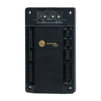
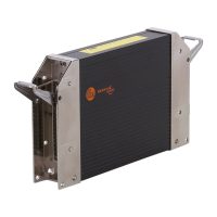
1.5. Mounting of the modules
In order to expose the controller modules to the minimum
mechanical stress they should preferably be mounted
horizontally or vertically on the mounting panel. The module
must be fixed with four screws to DIN 7500 or DIN 7984 (M5 x
L).
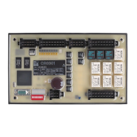
If possible, the modules should be mounted in such a way that
the cable entry of the plug points downwards.
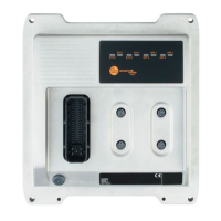
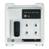
1.6. Electrical connection of the modules
Before commissioning it must be ensured that the following pins
must/can be connected to the corresponding potentials.
To guarantee the electrical interference protection of the
controller modules, the housings must be connected to
the ground of the vehicle.
1.7. Fusing of the controller modules
In order to protect the whole system (cabling and controller) the
individual circuits must be fused accordingly, taking into account
the total current of 10 A of the individual output modules (max. 8
outputs – e.g. QX0.08 ... QX0.15).
Designation Pin No. Potential
Supply voltage 23 (VBB
S
) + 24 V DC
Ground 01 (GND
S
) GND
Analog ground 12 (GND
A
) GND
Supply voltage
outputs High-Side
without monitoring relay
05 (VBBo) + 24 V DC
Supply voltage
outputs High-Side
with monitoring relay
34 (VBB
R
) + 24 V DC
Supply voltage
outputs Low-Side
without monitoring relay
15 (GNDo) GND
Test input,
programming mode
24 (Test) + 24 V DC
Test input, operating mode 24 (Test) open
Programming interface RS 232 06 (RxD) Pin 03, PC 9pin SUB-D
07 (TxD) Pin 02, PC 9pin SUB-D
33 (CM
5
) Pin 05, PC 9pin SUB-D
CAN interface 14 (CAN
H
) CAN
H
further participant
32 (CAN
L
) CAN
L
further participant
33 (CM
5
) GND further participant
 Loading...