page 15
2. The monitoring function
The safe operation of the controller outputs is ensured by the
monitoring function.
2.1. Hardware setup
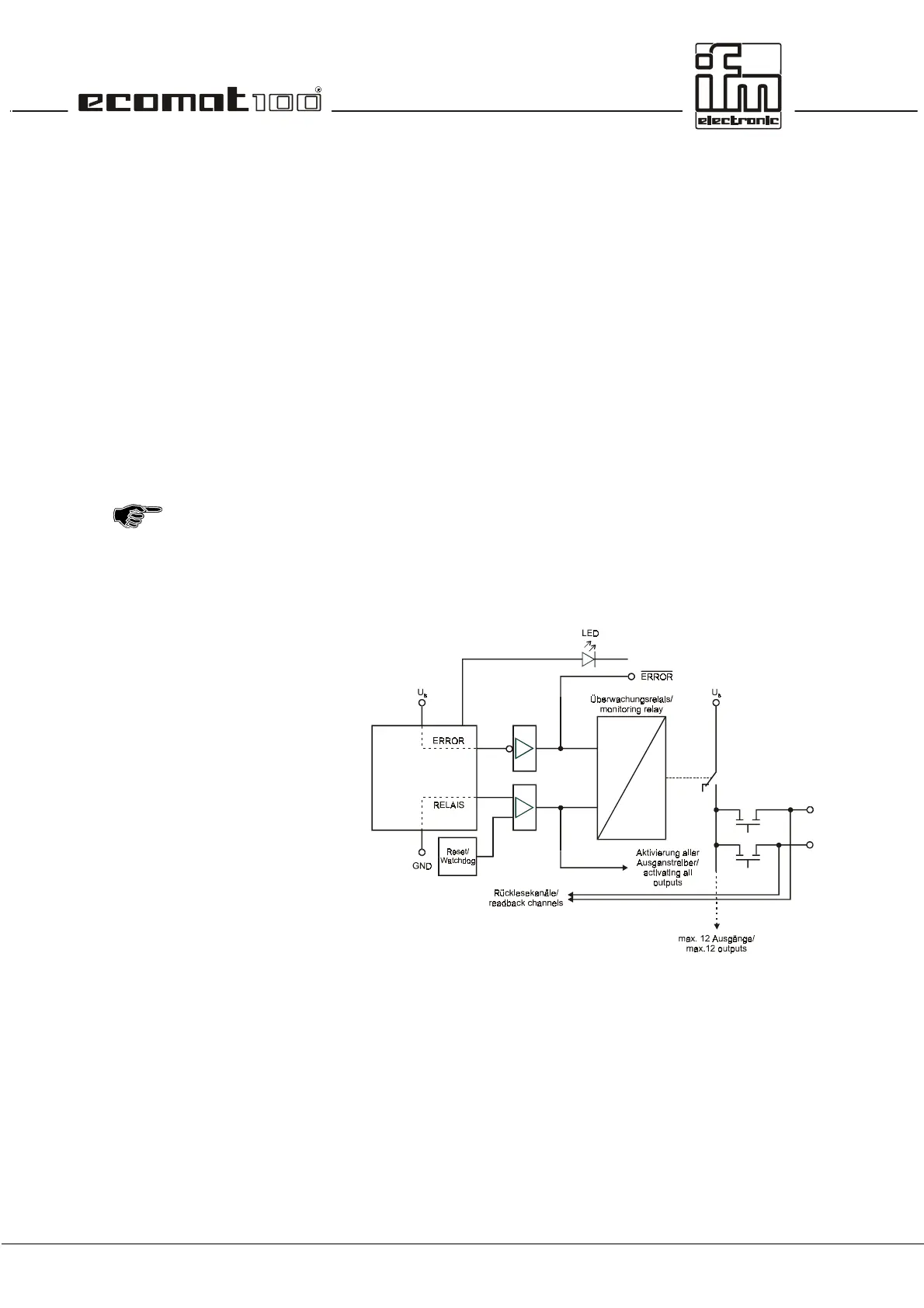
The relay is triggered on two channels via the µcontroller. For
this purpose the negative channel is triggered by means of an
AND link of the watchdog signal (internal µcontroller monitoring)
and the RELAY bit with a semiconductor switch. The positive
channel is only triggered by means of the ERROR bit via a
semiconductor switch. In the activated state the outputs to be
disconnected (max. 12) are connected to the supply voltage via
the relay contact (not forced)
In addition the output signal of the semiconductor switch has the
logical effect of a release signal for all outputs. These outputs
are only switched externally after the RELAY bit has been set.
Therefore the RELAY bit has to be set even if there is no
RELAY integrated in the hardware.
Schematic of the monitoring concept.
 Loading...