page 27
5. Error codes and error classes
In order to ensure maximum operational reliability the operating
system carries out internal error checks in the controller during
the start-up phase (reset phase) and during the program
execution.
The following error flags are set in the case of an error:
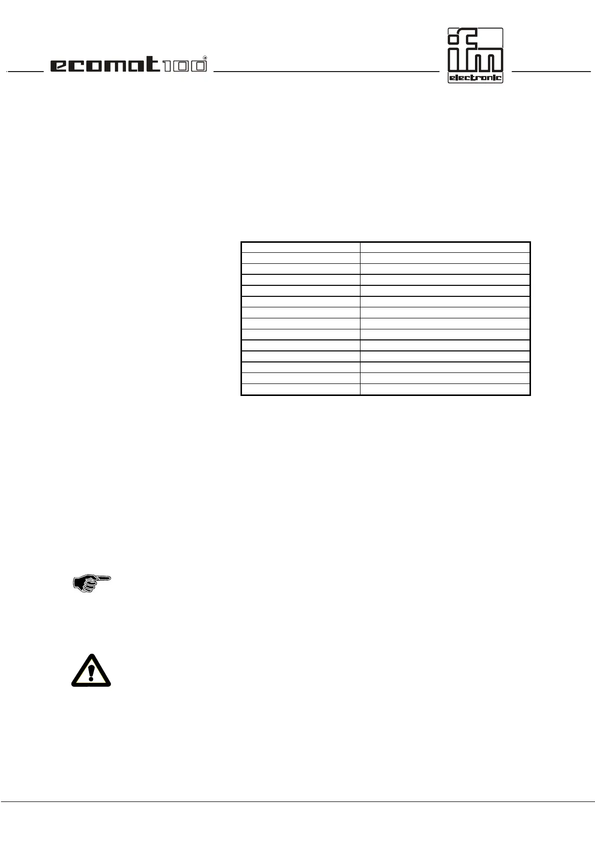
Error Error description
CAN_INIT_ERROR CAN module cannot be initialised
CAN_DATA_ERROR CAN inconsistent data
CAN_RX_OVERRUN_ERROR CAN overrun, received data
CAN_TX_OVERRUN_ERROR CAN overrun, transmission data
CAN_BUS_OFF_ERROR CAN not on the bus
CAN_ERROR CAN-Bus collective error bit
ERROR collective error bit (general)
ERROR_MEMORY memory error
ERROR_POWER under/overvoltage error
ERROR_TEMPERATURE excess temperature error (> 85°C)
COP_SYNCFAIL_ERROR SYNC object was not transferred
COP_GUARDFAIL_ERROR Guarding object is missing (only in the slave)
COP_GUARDFAIL_NODEID number of missing slave (only in the master)
5.1. Reaction to system error
It is the programmer's responsibility to react to error flags.
The specific error bits should be processed in the user program
and then have to be reset. The error bit provides an error
description which can be further processed if required.
In the case of severe errors the ERROR bit can be set causing
the operating LED to light red, the error output (pin 13) to be set
to LOW and the monitoring relay (if there is one) to be switched
off. The protected outputs are de-energised.
The logic link via the relay bit (see chapter 2) also switches
off all other outputs.
Depending on the application it has to be decided if the relay
and thus the outputs can be switched on again by resetting the
ERROR bit.
When using CAN for communication the function
CAN_ERRORHANDLER should be used. Thus all CAN errors
are detected as a collective error, are counted and CAN is
started again.
 Loading...