page 34
Bus level
The CAN bus is in the inactive (recessive) state if the output
transistor pairs are switched off in all bus participants. If at least
one transistor pair is switched on, a bit is sent to the bus which
then becomes active (dominant). Thus a current flows through
the terminating resistors and generates a different voltage
between the two bus cables. The recessive and dominant states
are converted into corresponding voltages in the bus nodes and
are detected by the receiver circuits.
l
This differential transmission with a common return line
considerably improves the transmission safety. Interfering
voltages which affect the system externally or mass potential
offsets influence both signal lines with the same interfering
quantities. They are therefore ignored when the difference is
formed.
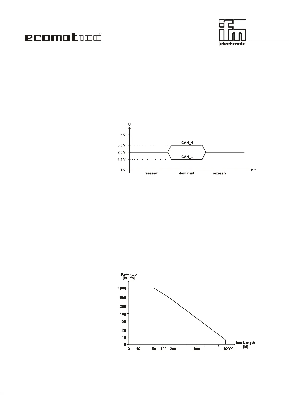
Bus cable length
The bus cable length depends on the characteristics of the bus
connection (cable, connector), the cable resistance and the
necessary transmission rate (baud rate). As described above,
the length of the spurs must also be considered for the network
design. For the sake of simplicity, the following dependence
between bus length and baud rate can be assumed.
 Loading...