page 87
7. PWM in the ecomat R 360
PWM is an abbreviation for Pulse Width Modulation. In the field
of controllers for mobile and robust applications it is mainly used
for triggering proportional valves (PWM valves). Furthermore,
an analog output voltage can be generated from the pulse-width
modulated output signal by adding (accessory) a PWM output.
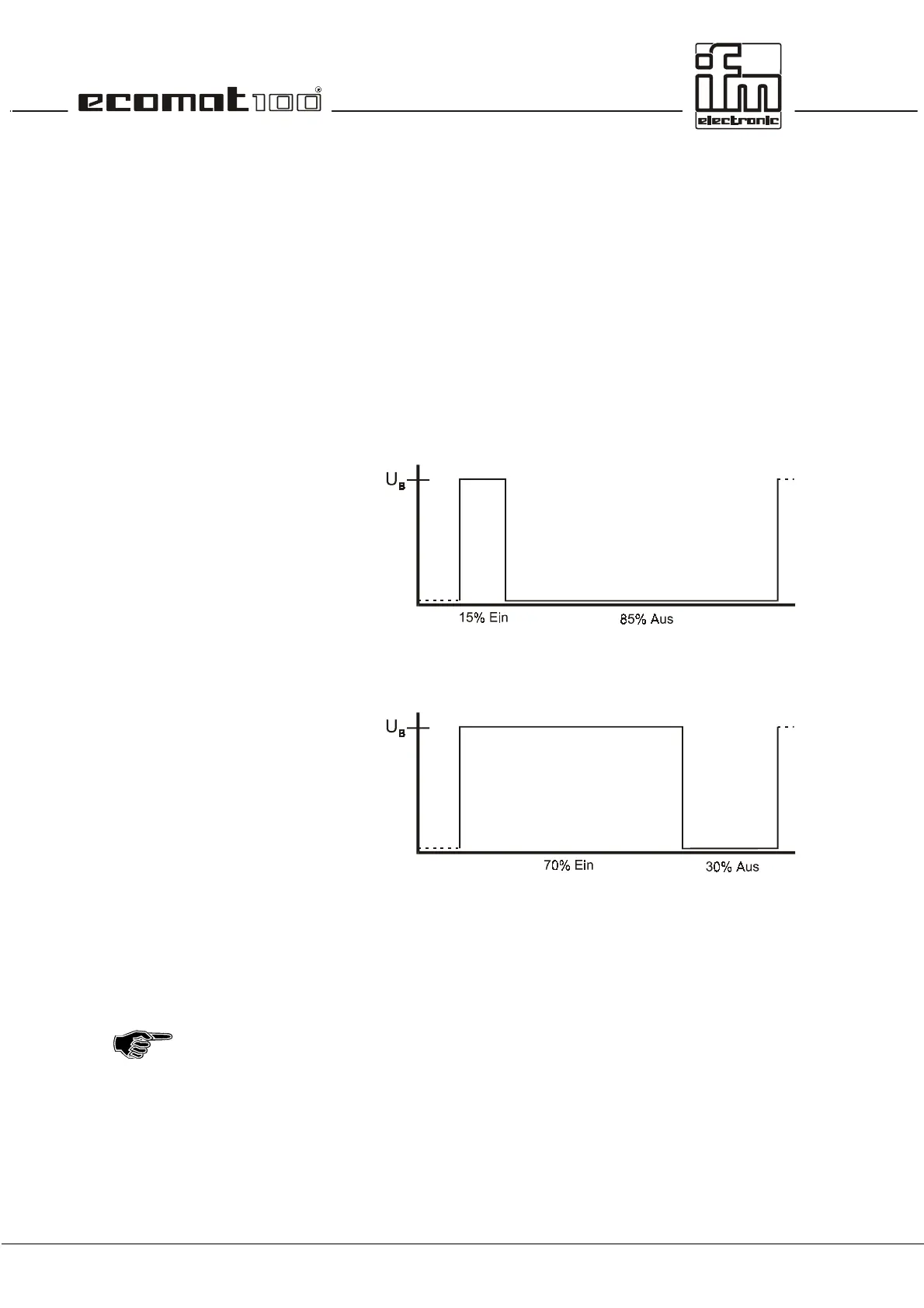
The PWM output signal is a pulsed signal between GND and
supply voltage. The pulse/break ratio is varied within a defined
period (PWM frequency). The current flowing through the
connected load depends on the pulse/break ratio.
The PWM function of the controller ecomat R 360 is a hardware
function provided by the
µ
controller. In order to use the 8
integrated PWM outputs of the controller they need to be
initialised in the user program and to be parameterised in
accordance with the requested output signal.
If the PWM function is used
all
4 outputs in a group (0...3 and
4...7) are switched in the PWM mode. That means that even
unused channels can no longer be used as digital inputs or
outputs.
 Loading...