MAINTENANCE
3.
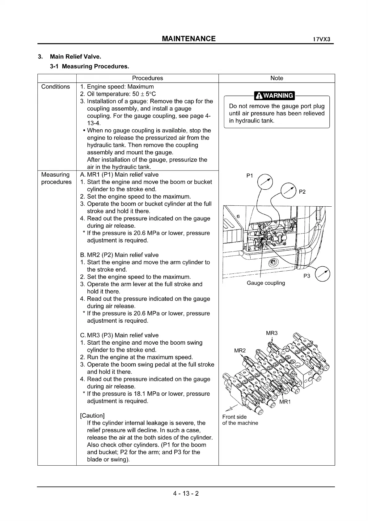
Main Relief Valve.
3-1
Measuring Procedures.
Procedures
17VX3
Note
Conditions
Measuring
procedures
1.
Engine speed: Maximum
2.
Oil temperature: 50 ± 5°C
3.
Installation
of
a gauge: Remove the cap for the
coupling assembly, and install a gauge
coupling. For the gauge coupling, see page 4-
13-4.
• When no gauge coupling is available, stop the
engine to release the pressurized air from the
hydraulic tank. Then remove the coupling
assembly and mount the gauge.
After installation
of
the gauge, pressurize the
air
in
the hydraulic tank.
A.
MR1
(P1) Main relief valve
1.
Start the engine and move the boom or bucket
cylinder to the stroke end.
2.
Set the engine speed to the maximum.
3.
Operate the boom or bucket cylinder at the full
stroke and hold it there.
4.
Read out the pressure indicated on the gauge
during air release.
*
If
the pressure
is
20.6 MPa or lower, pressure
adjustment is required.
B.
MR2 (P2) Main relief valve
1.
Start the engine and move the arm cylinder to
the stroke end.
2.
Set the engine speed to the maximum.
3.
Operate the arm lever at the full stroke and
hold it there.
4.
Read out the pressure indicated on the gauge
during air release.
* If the pressure
is
20.6 MPa or lower, pressure
adjustment is required.
,----
------.,.
Do not remove the gauge port plug
until air pressure has been relieved
in
hydraulic tank.
Gauge coupling
C.
MR3 (P3) Main relief valve
1.
Start the engine and move the boom swing
cylinder to the stroke end.
2.
Run the engine at the maximum speed.
3.
Operate the boom swing pedal at the full stroke
and hold it there.
4.
Read out the pressure indicated on the gauge
during air release.
*
If
the pressure
is
18.1
MPa
or
lower, pressure
adjustment is required.
[Caution]
Front side
If the cylinder internal leakage is severe, the
of
the machine
relief pressure will decline.
In
such a case,
release the air at the both sides
of
the cylinder.
Also check other cylinders.
(P1
for the boom
and bucket;
P2
for the arm; and P3 for the
blade or swing).
4-13-2
 Loading...