STRUCTURE
17VX3
Item Parts name
O'ty
1 Boom 50
kg
1
2 Arm STD. 27
kg
1
Arm LONG 36
kg
1
3
Arm cylinder 1
4 Bucket cylinder 1
5
Arm link (R.H) 1
6
Arm link (L.H) 1
7 Bucket link 1
8
Wing pin 2
9
Head pin 1
10 Wing pin 2
11
Head pin 2
12 Head pin 1
13 Head pin 1
14 Wing pin 1
15 Wing pin 1
16 Ring pin 2
17 Cover 1
18
Stay
1
19 Sintering bushing 2
20 Steel bushing 2
21
Sintering bushing
8
22 Spacer
3
23 Spacer 1
24 Bushing 2
25 Bushing 4
26 Spacer 1
27 Oring 4
28 Collar 2
29 Cotter pin 1
30
Castle nut 1
31
F.
HT (S) nut 4
32
F.
HT (S) bolt 2
33
F.
HT (S) bolt 2
34 HT (S) bolt 2
35
HT (S) bolt 4
36
Spring washer 2
37 Grease fitting
6
38
Resin washer 7
39
Resin washer 7
40 Resin washer 4
41
Washer 1
42 Washer 2
43 Washer 2
44 Washer 2
46 HT (S) bolt 2
37
Clearance 1
E
24
9
24
34
L
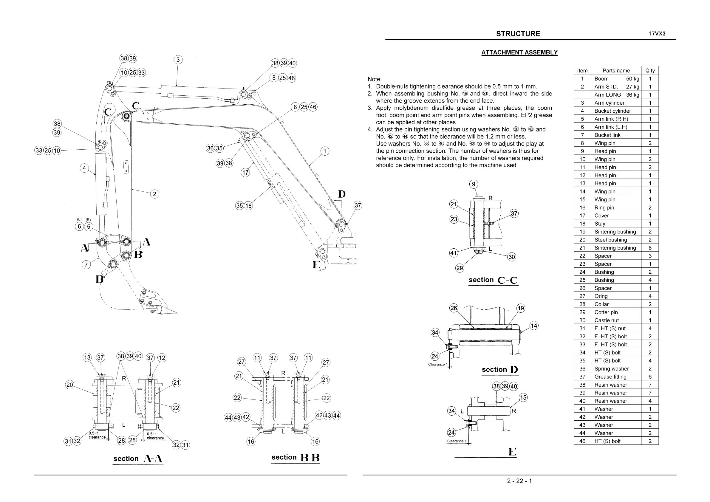
ATTACHMENT
ASSEMBLY
34
Clearance 1
section D
Note:
1.
Double-nuts tightening clearance should be 0.5
mm
to 1 mm.
2.
When
assembling bushing No. @ and ®, direct inward the side
where
the
groove
extends from the end face.
3.
Apply
molybdenum
disulfide grease
at
three places, the boom
foot, boom point and arm point pins
when
assembling. EP2
grease
can be applied
at
other
places.
4.
Adjust
the pin tightening section using
washers
No. @ to ® and
No.
© to @ so that the clearance will be 1.2
mm
or
less.
Use
washers
No. @ to ® and No. © to @ to adjust the play
at
the pin connection section.
The
number
of
washers
is thus
for
reference only.
For
installation, the
number
of
washers
required
should be determined according to the machine used.
22
42 43 44
?
21
16
8 25 46
38 39 40
section B-B
16
36 35
21
32
31
22
\0
~----
__
J
38 39
section A-A
30
29
section
C-C
\
\
\
-----
26
.......
_---
38
39
33
25
10
2 - 22 - 1