MAINTENANCE
17VX3
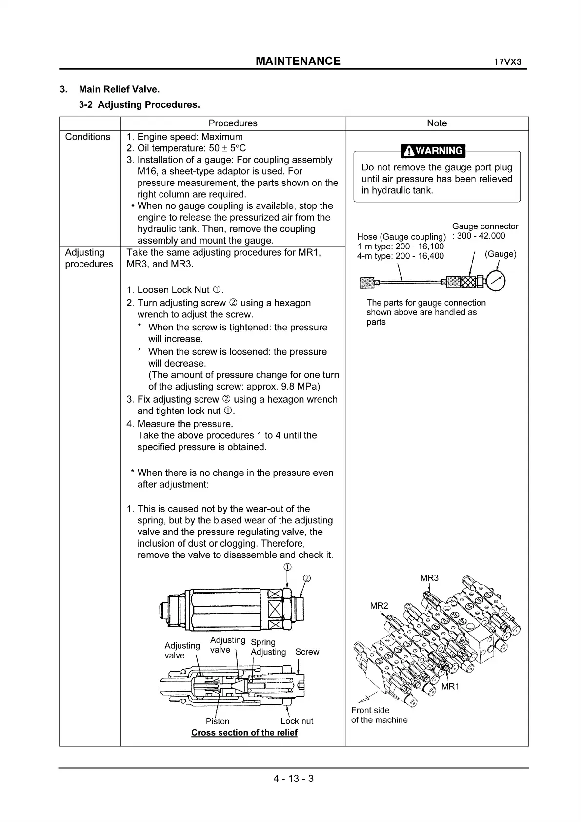
3.
Main Relief Valve.
3-2
Adjusting
Procedures.
Procedures Note
Conditions
Adjusting
procedures
1.
Engine speed: Maximum
2.
Oil temperature: 50 ± 5°C
3.
Installation
of
a gauge: For coupling assembly
M16, a sheet-type adaptor is used. For
pressure measurement, the parts shown on the
right column are required.
• When no gauge coupling is available, stop the
engine to release the pressurized air from the
hydraulic tank. Then, remove the coupling
assembly and mount the gauge.
Take the same adjusting procedures for MR1,
MR3, and MR3.
1.
Loosen Lock Nut
CD.
2.
Turn adjusting screw
~
using a hexagon
wrench to adjust the screw.
* When the screw
is
tightened: the pressure
will increase.
* When the screw is loosened: the pressure
will decrease.
(The amount
of
pressure change for one turn
of
the adjusting screw: approx. 9.8 MPa)
3.
Fix adjusting screw ~ using a hexagon wrench
and tighten lock nut
CD.
4.
Measure the pressure.
Take the above procedures 1 to 4 until the
specified pressure is obtained.
,----
------.,.
Do not remove the gauge port plug
until air pressure has been relieved
in
hydraulic tank.
Gauge connector
Hose (Gauge coupling) : 300 - 42.000
1-m type: 200 - 16,100
4-m type: 200 - 16,400
\
The parts for gauge connection
shown above are handled as
parts
* When there is no change
in
the pressure even
after adjustment:
1.
This
is
caused not by the wear-out
of
the
spring, but by the biased wear
of
the adjusting
valve and the pressure regulating valve, the
inclusion
of
dust or clogging. Therefore,
remove the valve to disassemble and check
it.
Front side
of the machine
Piston Lock nut
Cross
section
of
the relief
4-13-3
 Loading...