MAINTENANCE
4.
Over
load Relief Valve.
4-1
Measuring Procedures.
Procedures
17VX3
Note
Conditions
Measuring
procedures
1.
Engine speed: Low idling
The set flow rate
of
this valve is 5 liters/min. and
the flow rate becomes higher than the set value at
a high engine speed,
in
which case higher
pressures are indicated. Be sure to run the engine
at a low speed.
2.
Oil temperature: 50 ± 5°C
3.
Installation
of
a gauge: Remove the cap for the
coupling assembly, and install a gauge coupling.
• When no gauge coupling is available, stop the
engine to release the pressurized air from the
hydraulic tank. Then, remove the coupling
assembly and mount the gauge. After installation
of
the gauge, pressurize the air
in
the hydraulic
tank.
4.
Set pressures: See the table for the set pressures.
5.
Set the main relief pressure temporarily.
The overload relief pressure is set higher than the
main relief pressure. Therefore, the main relief
pressure needs to be set higher than the overload
relief pressure.
Temporary setting
of
the main relief pressure
1) Loosen the lock nut for main relief pressure and
tighten the adjusting screw by 180° to tighten the
tightening lock nut.
2) After adjusting the overload relief pressure, loosen
the lock nut for main relief pressure, loosen the
adjusting screw by 180°
or
more. Return the
pressure to the set value or less and thereafter
make ad'ustments at the
ti
htenin side.
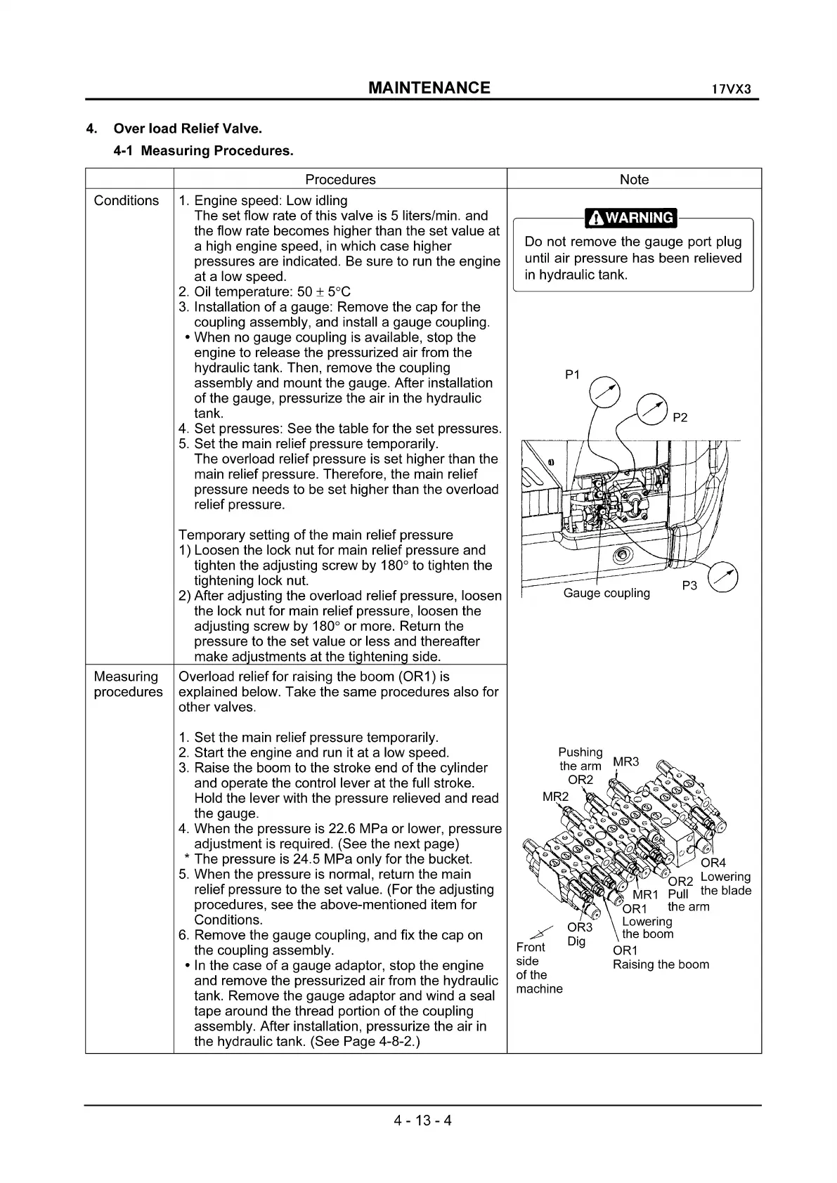
Overload relief for raising the boom (OR1) is
explained below. Take the same procedures also for
other valves.
,,----
--------.,.
Do not remove the gauge port plug
until air pressure has been relieved
in
hydraulic tank.
P1
Gauge coupling
1.
Set the main relief pressure temporarily.
2.
Start the engine and run it at a low speed.
3.
Raise the boom to the stroke end
of
the cylinder
and operate the control lever at the full stroke.
Hold the lever with the pressure relieved and read
the gauge.
4.
When the pressure is 22.6 MPa
or
lower, pressure
adjustment is required. (See the next page)
* The pressure is 24.5 MPa only for the bucket.
5.
When the pressure is normal, return the main
relief pressure to the set value. (For the adjusting
procedures, see the above-mentioned item for
Conditions.
6.
Remove the gauge coupling, and fix the cap on
the coupling assembly.
•
In
the case
of
a gauge adaptor, stop the engine
and remove the pressurized air from the hydraulic
tank. Remove the gauge adaptor and wind a seal
tape around the thread portion
of
the coupling
assembly. After installation, pressurize the air
in
the hydraulic tank. (See Page 4-8-2.)
4-13-4
/
Front
side
of the
machine
OR4
D
(J
~OR2
Lowering
MR1
Pull the blade
"OR1
the arm
Lowering
the boom
OR1
Raising the boom
 Loading...