MAINTENANCE
17VX3
4.
Over
load Relief Valve.
4-2
Adjusting
Procedures.
Procedures Note
~---
-------....
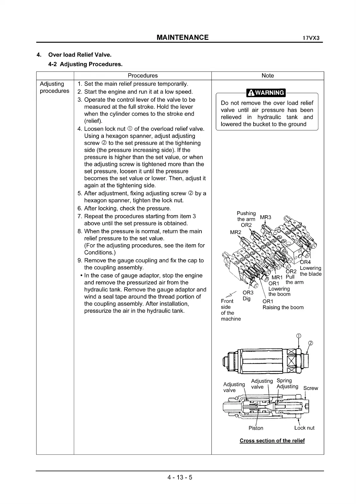
Do not remove the over load relief
valve until air pressure has been
relieved
in
hydraulic tank and
lowered the bucket to the ground
OR3
Dig
~
R4
o
t1
~R2
Lowering
WN~~~;TMR1
Pull
the
blade
OR1 the
arm
Lowering
the
boom
OR1
Raising
the
boom
/
Front
side
of
the
machine
1.
Set the main relief pressure temporarily.
2.
Start the engine and run it at a low speed.
3.
Operate the control lever
of
the valve to be
measured at the full stroke. Hold the lever
when the cylinder comes to the stroke end
(relief).
4.
Loosen lock nut
CD
of
the overload relief valve.
Using a hexagon spanner, adjust adjusting
screw
~
to the set pressure at the tightening
side (the pressure increasing side). If the
pressure
is
higher than the set value, or when
the adjusting screw
is
tightened more than the
set pressure, loosen it until the pressure
becomes the set value or lower. Then, adjust it
again at the tightening side.
5.
After adjustment, fixing adjusting screw ~ by a
hexagon spanner, tighten the lock nut.
6.
After locking, check the pressure.
7.
Repeat the procedures starting from item 3
above until the set pressure
is
obtained.
8.
When the pressure
is
normal, return the main
relief pressure to the set value.
(For the adjusting procedures, see the item for
Conditions.)
9.
Remove the gauge coupling and fix the cap to
the coupling assembly.
•
In
the case
of
gauge adaptor, stop the engine
and remove the pressurized air from the
hydraulic tank. Remove the gauge adaptor and
wind a seal tape around the thread portion
of
the coupling assembly. After installation,
pressurize the air
in
the hydraulic tank.
Adjusting
procedures
Piston
Lock
nut
Cross
section
of
the
relief
4-13-5