MAINTENANCE
17VX3
5.
Swing
Relief Valve
pressure
Measuring
&
Adjusting
Procedures.
Procedures Note
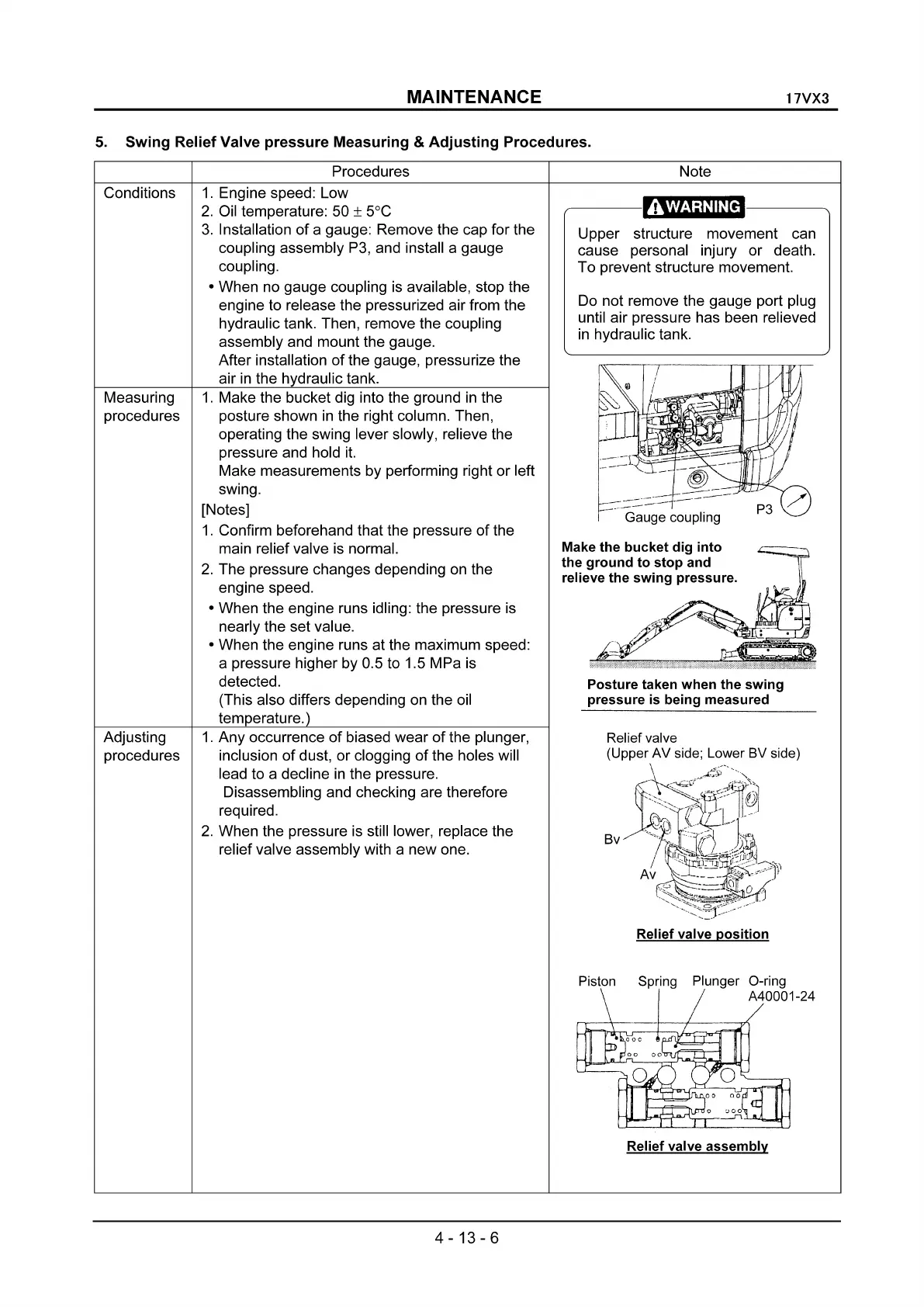
Gauge coupling
Posture
taken
when
the
swing
pressure
is being measured
.,,----
-----....
Upper structure movement can
cause personal injury or death.
To prevent structure movement.
Do not remove the gauge port plug
until air pressure has been relieved
in
hydraulic tank.
Make
the
bucket
dig
into
the
ground
to
stop
and
relieve
the
swing
pressure.
1.
Engine speed: Low
2.
Oil temperature: 50 ± 5°C
3.
Installation of a gauge: Remove the cap for the
coupling assembly
P3,
and install a gauge
coupling.
• When no gauge coupling
is
available, stop the
engine to release the pressurized air from the
hydraulic tank. Then, remove the coupling
assembly and mount the gauge.
After installation
of
the gauge, pressurize the
air
in
the hydraulic tank.
1.
Make the bucket dig into the ground
in
the
posture shown
in
the right column. Then,
operating the swing lever slowly, relieve the
pressure and hold
it.
Make measurements by performing right or left
swing.
[Notes]
1.
Confirm beforehand that the pressure
of
the
main relief valve
is
normal.
2. The pressure changes depending
on
the
engine speed.
• When the engine runs idling: the pressure
is
nearly the set value.
• When the engine runs at the maximum speed:
a pressure higher by 0.5 to 1.5 MPa
is
detected.
(This also differs depending on the oil
temperature.)
Conditions
Measuring
procedures
Adjusting
procedures
1.
Any occurrence
of
biased wear
of
the plunger,
inclusion
of
dust, or clogging
of
the holes will
lead to a decline
in
the pressure.
Disassembling and checking are therefore
required.
2.
When the pressure
is
still lower, replace the
relief valve assembly with a new one.
Piston Spring Plunger O-ring
A40001-24
Relief valve
assembly
4-13-6