www.ikegps.com/quickstart Page 8 www.ikegps.com/support
Anatomy of the ike unit
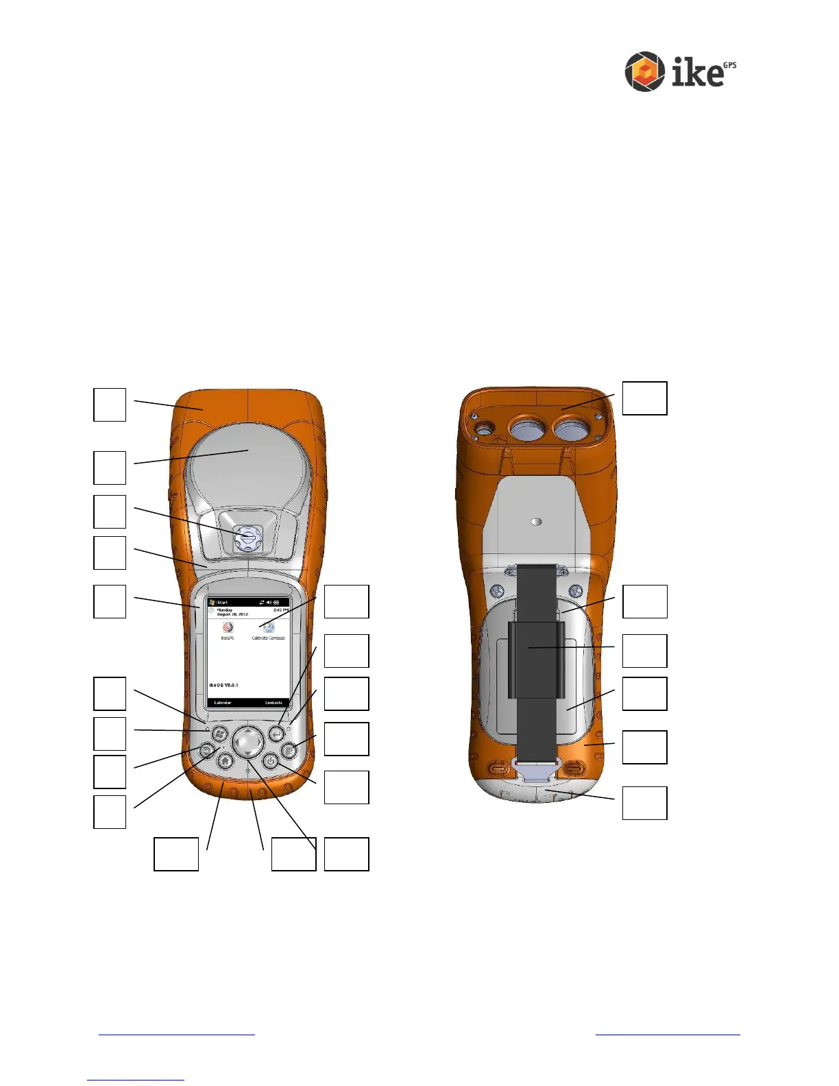
This section illustrates the different parts of ike.
1 Elastomer overmold
2 GPS Receiver and Antenna
3 Removable SD Card Slot Cover
4 Magnesium case front
5 ike model bezel label
6 Charge indicator (red LED)
7 Start menu button *
8 Task Manager button *
9 Microphone
10 Today screen button *
11 Speaker
12 Four-way directional button
13 Power button
14 Context menu button *
15 Notification indicator (green LED)
16 Enter button
17 Touchscreen/LCD display
18 Laser ‘Reference Plane’ – distance
measured from this surface
19 Battery door latch
20 Hand strap
21 Battery door
22 Body molding
23 Connector Protector
* Buttons 7, 8, 10 & 14 may be reprogrammed for alternate functions depending on application being used.