4. Press the “0” and “7” number key while simultaneously powering the
instrument on.
5. Set the output voltage to “0” volts in the low voltage range and activate the
output of the instrument.
6. Adjust VR3 on the PWMAC300 board so that the DVM measures “0” volts
+\- 10mV.
7. Then, set the output voltage to “110” volts in the low voltage range and
activate the output of the instrument.
8. Adjust VR3 on the ANGAC300 board so that the DVM measures “0” volts
+\- 20mV.
9. Reset the output.
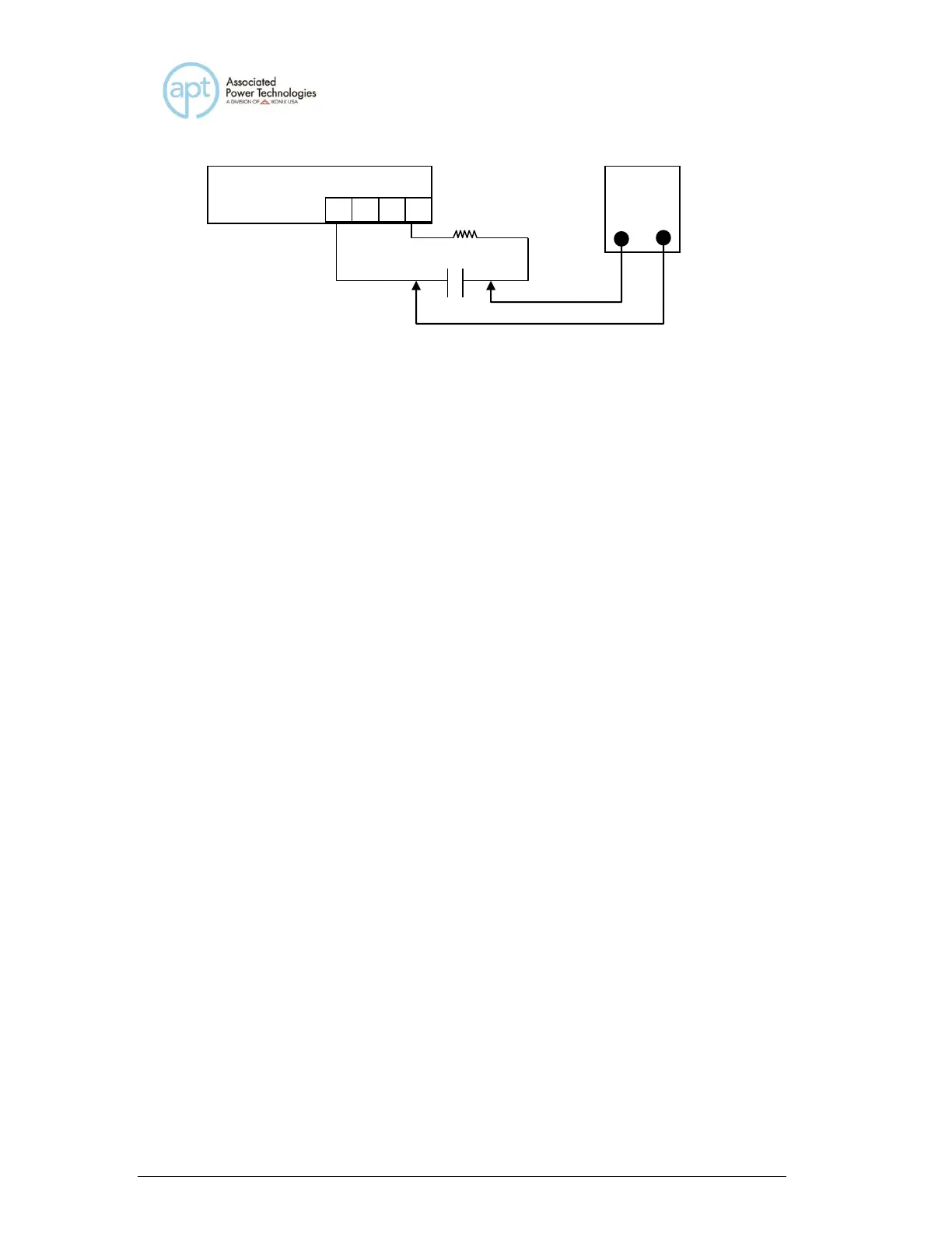
10. Connect the 475kΩ resistor in series with the 10uf capacitor to the
instrument output B and N.
11. Set the output voltage to “0” volts in the low voltage range and activate the
output of the instrument.
12. Adjust VR2 on the PWMAC300 board so that the DVM measures “0” volts
+\- 10mV
13. Then, set the output voltage to “110” volts in the low voltage range and
activate the output of the instrument.
14. Adjust VR2 on the ANGAC300 board so that the DVM measures “0” volts
+\- 20mV.
15. Reset the output.
16. Connect the 475kΩ resistor in series with the 10uf capacitor to the
instrument output C and N.
17. Set the output voltage to “0” volts in the low voltage range and activate the
output of the instrument.
18. Adjust VR1 on the PWMAC300 board so that the DVM measures “0” volts
+\- 10mV
19. Then, set the output voltage to “110” volts in the low voltage range and
activate the output of the instrument.
20. Adjust VR1 on the ANGAC300 board so that the DVM measures “0” volts
+\- 20mV.
21. Disconnect the load and the DVM.
22. Powering the instrument off then remove JP1.
 Loading...