35
INSTALLER
USERMAINTENANCE TECHNICIAN
TECHNICAL DATA
A
B
A
C
37
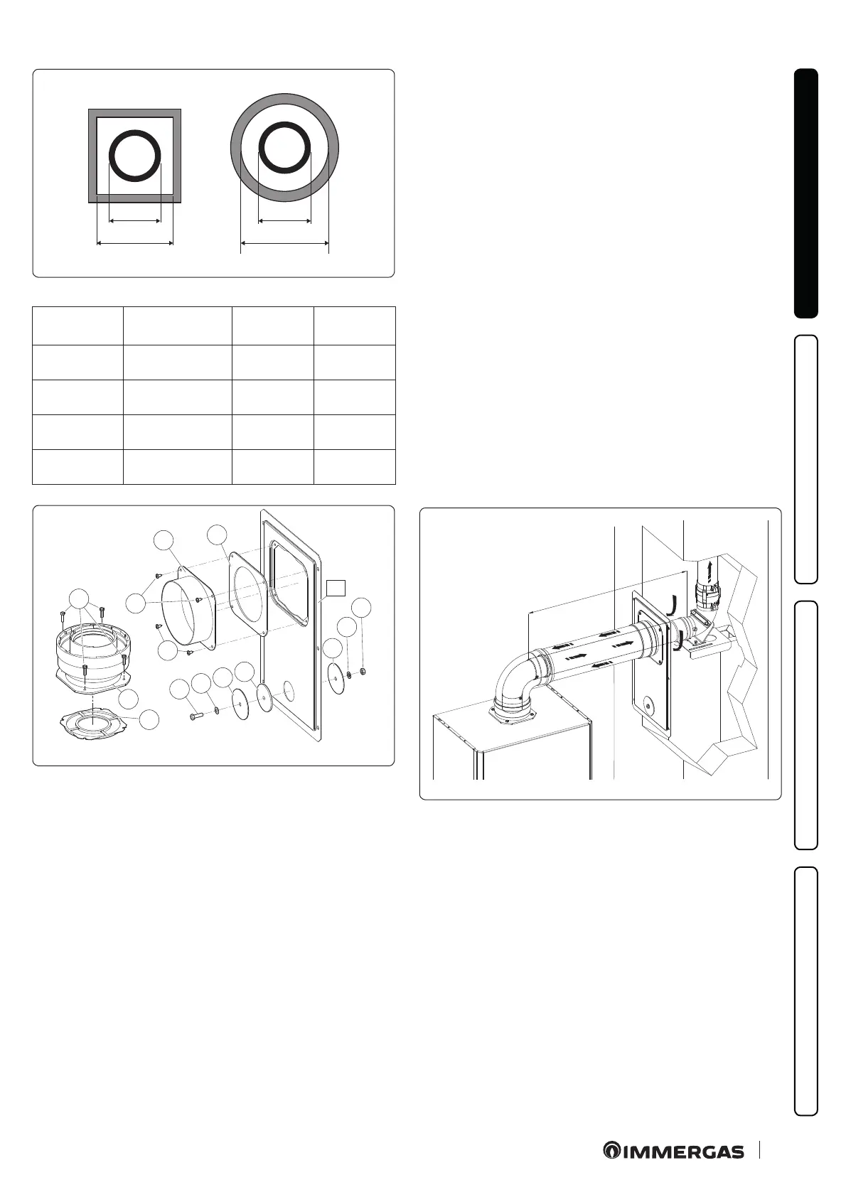
Ducting
ADAPTOR
(A) mm
SHAFT
(B) mm
SHAFT
(C) mm
Ø 60
Rigid
66 106 126
Ø 50
Flexible
66 106 126
Ø 80
Rigid
86 126 146
Ø 80
Flexible
103 143 163
1
2
3
3
4
5
6
7
6
8
9
A
10
11
12
38
e adapter kit includes (Fig. 38):
No.1 Door adaptor Ø 100 or Ø 125 (1)
N o .1 D o o r g a s k e t m a d e o f n e o p r e n e ( 2)
No.4 Screws 4.2 x 9 ST (3)
No.1 Hex headed screw M6 x 20 (4)
N o .1 F l a t n y l o n w a s h e r M 6 (5)
No.2 Door hole closure metal-sheet plate plug (6)
N o .1 P l u g g a s k e t m a d e o f n e o p r e n e ( 7 )
No.1 Toothed washer M6 (8)
No.1 M6 nut (9)
No.1 (kit Ø 80/125) Concentric gasket Ø 60/100 (10)
No.1 (kit Ø 80/125) Flanged adapter Ø 80/125 (11)
No.4 (kit Ø 80/125) Hexagon-head screws M4 x 16 at-tip screwdriver
(12)
No.1 (kit Ø 80/125) Bag of lubricating talc
Supplied separately (Fig. 38):
No.1 Ducting kit door (A)
Tec hn ic a l d at a
e dimensions of the shas must ensure a minimum gap be-
tween the outer wall of the smoke duct and the inner wall of the
sha: 30 mm for circular section shas and 20 mm in the event of
a square section sha (Fig. 37).
Maximum 2 changes of direction are allowed on the vertical sec-
tion of the ue system with a maximum clearance angle of 30°
with respect to the vertical.
e maximum vertical extension using a Ø 60 ducting system is
12.9 m, the maximum extension includes 1 bend Ø 60/100 at 90°,
1 m of horizontal pipe Ø 60/100, 1 x 90° ducted bend Ø 60 and the
roof terminal for ducting.
e maximum vertical extension using a Ø 80 rigid ducting sys-
tem is 28 m, the maximum extension includes 1 adapter from
Ø 60/100 to Ø 80/125, 1 bend Ø 80/125 of 87°, 1 m of pipe
Ø 80/125 in horizontal, 1 x 90° ducted bend Ø 80 and the roof ter-
minal for ducting.
To determine the C
93
ue system in congurations other than that
described (Fig. 39) one must consider the following head losses:
- 1 m of concentric pipe Ø 80/125 = 1.8 m of rigid ducted pipe
Ø 80 and 0.7 m of exible ducted pipe Ø 80;
- 1 curve Ø 80 of 87° = 2.1 m of rigid ducted pipe Ø 80 and 0.9 m
of exible ducted pipe Ø 80.
Consequently one must subtract the equivalent length of the part
added to the 28 m available.
C
93
X
39

 Loading...


