59
INSTALLER
USERMAINTENANCE TECHNICIAN
TECHNICAL DATA
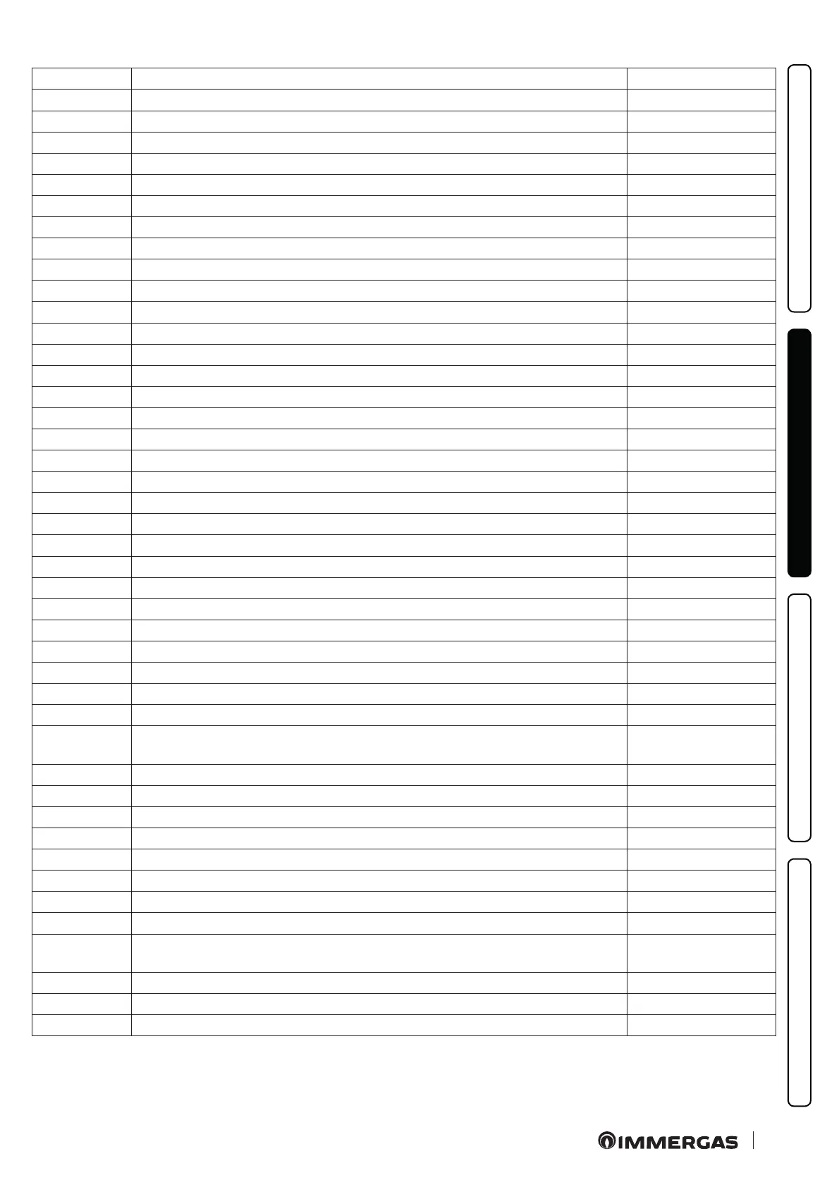
Parameter ID Description Range
D 25 Zone 2 ow temperature (if congured) 0 ÷ 99 °C
D 26 Probe for primary solar storage (puer) 0 ÷ 99 °C
D 27 Primary circuit pressure switch OFF - ON
D 28 Heat pump circulator DHW speed 0 ÷ 100 %
D 29 Flue probe 0 ÷ 100 °C
D 34 Heat pump disabling OFF - ON
D 35 Solar system inlet OFF - ON
D 36 Not used
D 41 Relative humidity zone 1 (if zone 1 humidity sensor active) 0 ÷ 99 %
D 42 Relative humidity zone 2 (if zone 2 humidity sensor active) 0 ÷ 99 %
D 43 Zone 1 humidistat (if zone 1 humidistat active) OFF - ON
D 44 Zone 2 humidistat (if zone 2 humidistat active) OFF - ON
D 45 Dehumidier zone 1 OFF - ON
D 46 Dehumidier zone 2 OFF - ON
D 47 Zone 1 circulator pump OFF - ON
D 48 Zone 2 circulator pump OFF - ON
D 49 Central heating / cooling system separation 3-way (CL = cooling, HT = heating) CL - HT
D 51 Zone 1 remote panel OFF - ON
D 52 Zone 2 remote panel OFF - ON
D 5 3 S y s t e m s e t t i n g w i t h r e m o t e c o n n e c t i o n i n z o n e 1 5 ÷ 8 0 ° C
D 5 4 S y s t e m s e t t i n g w i t h r e m o t e c o n n e c t i o n i n z o n e 2 5 ÷ 8 0 ° C
D 55 Zone 1 thermostat OFF - ON
D 56 Zone 2 thermostat OFF - ON
D 61 System model denition ( MP = Magis Pro; MCI = Magis Combo; MCP = Magis Combo Plus) MP - MCI - MCP
D 62 Communication with outdoor unit interface board OFF - ON
D 63 Communication with other Immergas devices OFF - ON
D 71 External unit operating frequency 0 ÷ 150 Hz
D 72 Compressor temperature -20 ÷ 200 °C
D 73 Compressor discharge temperature -20 ÷ 100 °C
D 74 Evaporator coil temperature -20 ÷ 100 °C
D 75
Outdoor unit compressor absorption (make sure the value reading refers to the inverter and there-
fore not a value read with an amperometric clamp)
0 ÷ 10 A
D 76 Outdoor unit fan speed 0 ÷ 100 rpm
D 77 Electronic expansion valve position 0 ÷ 2000
D 78 4-way side (CL = cooling, HT = heating) HT / CL
D 79 Temperature detected by the external probe of the outdoor unit -55°÷ +45°C
D 80 Heat pump status (reserved for Technical Assistance Service) 0 ÷ 255
D 91 P.C.B. soware version 30
D 92 Ignition board soware version
D 97 Heat pump demand status (reserved for Technical Assistance Service) 0 ÷ 999
D 98
ermal generator demand status (reserved for Authorised Aer-Sales Technical Assistance
Centre)
0 ÷ 999
D 99 System state (reserved to Authorised Aer-Sales Technical Assistance Centre) 0 ÷ 999
D101 Zone 3 ow temperature (if applicable) 1 ÷ 99
D102 Zone 3 relative humidity (if available) 1 ÷ 99
 Loading...


