Installation Manual
22 Internal devices
4.6 The SmartLoop/PSTN board
The SmartLoop/PSTN board allows the SmartLoop fire control panel to use the land line (PSTN). It
manages (and monitors) 2 lines and uses the most widely used reporting protocols (SIA, Contact ID,
etc.). It has an 8-slot audio memory for up to eight voice call messages. Completely managed by its
on-board microcontroller, it generates emergency calls in the event of CPU fault, and also any alarm
calls triggered during the CPU fault.
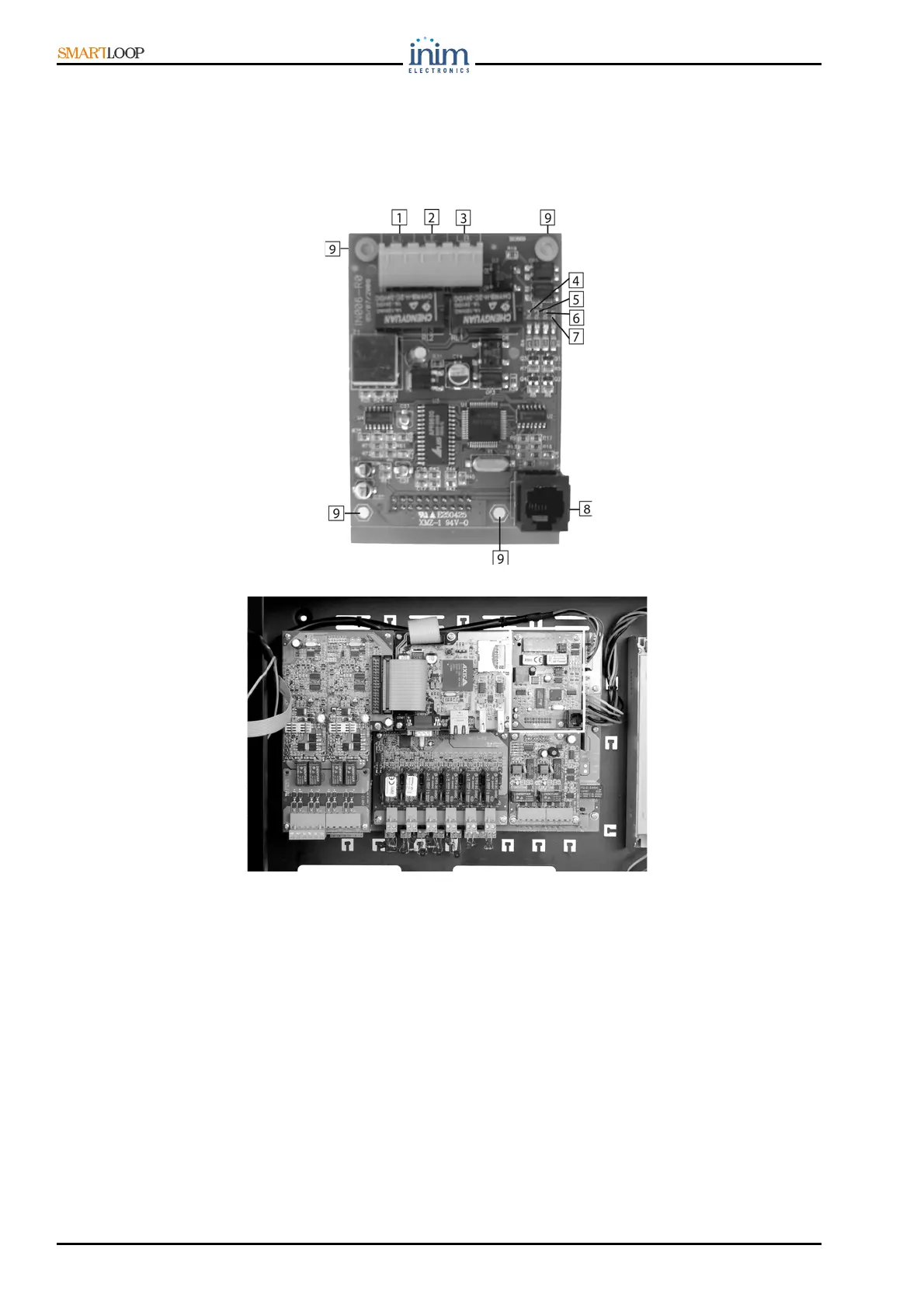
Figure 13 - The SmartLoop/PSTN board
Figure 14 - The SmartLoop/PSTN board location on the motherboard
4.6.1 The SmartLoop/PSTN board components
1. Internal telephone line terminals: provides line voltage to the connected telephone devices, the LE
line must be connected to these terminals.
2. External telephone line terminal: for the telephone line connection
3. Backup line terminal: for the connection of a secondary line to be used in the event of "primary
line-down" conditions.
4. Backup line fault LED
5. Primary telephone-line fault LED
6. Activity LED (indicates data exchange between the SmartLoop/PSTN board and the motherboard)
7. Line-hooked LED (goes On when the PSTN board engages the phone line)
8. Phone plug-in connector (for recording voice messages using a normal phone)
9. Board screws (4)