Installation Manual
42 Connections
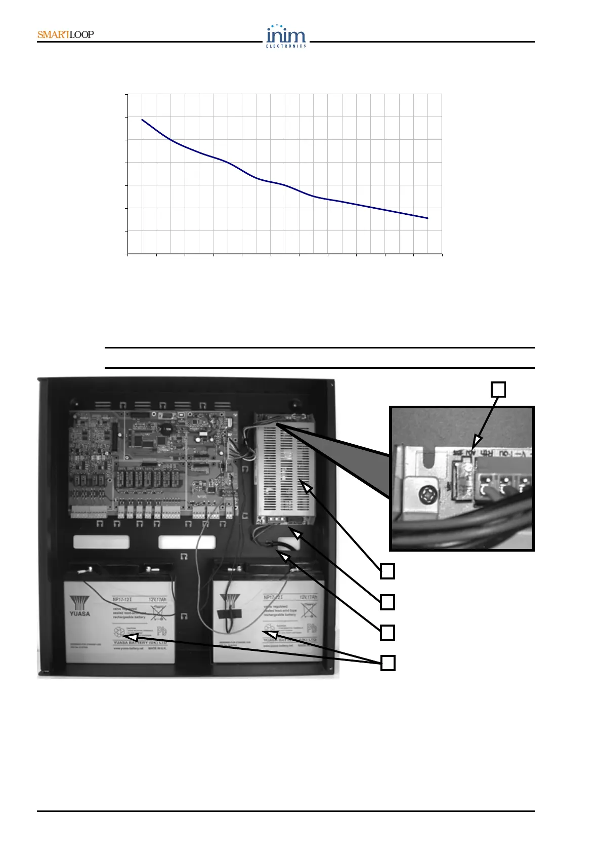
Figure 39 - Charge Voltage in relation to Battery Temperature
7.21 Connecting to the Mains power source (Electrical Switchboard)
The power system of the SmartLoop control panel is EN54-4 compliant.
Danger: DO NOT power up the system with a non-compliant voltage (see label).
Figure 40 - Mains power and battery connections and trimmer details
For a safety standards compliant system, the Line must be connected to terminal [ACL], Neutral to
terminal [ACN] and Earth to terminal [FG].
This panel must be connected to a separate line on the Electrical Switchboard (Mains power supply).
The line must be protected by a sectioning device which complies with local safety regulations, fire
codes, laws and bylaws in force.
25,5
26
26,5
27
27,5
28
28,5
29
0 5 10 15 20 25 30 35 40 45 50
°C
Volt
2
1
3
4
5