Installation Manual
36 Connections
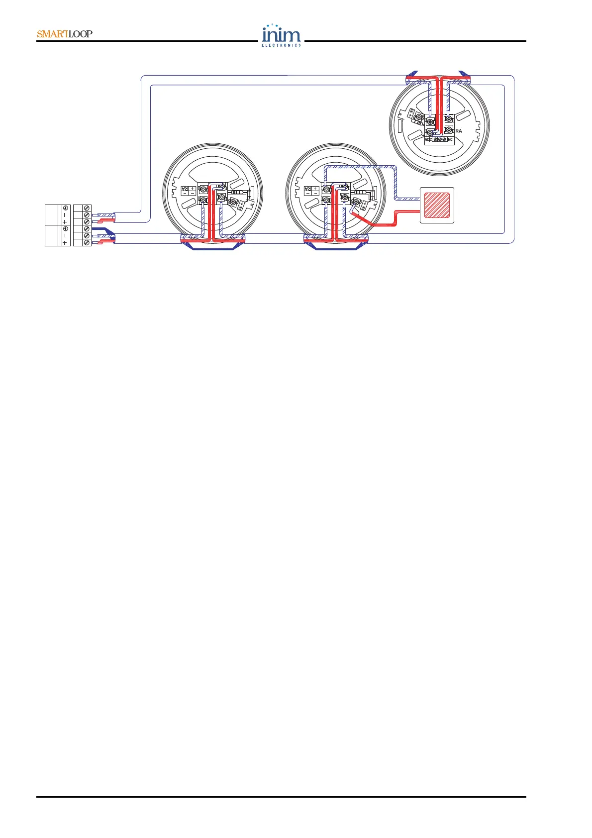
Figure 30 - 4 wire connection
7.7 NAC Outputs (Notification Application Circuit)
7.7.1 Alarm NAC
Alarm NAC output (30) protected by 1 A resettable fuse: Supervised, Silenceable output
To be connected to: ALARM signaling devices.
Operating principles
This output will activate when FIRE ALARM conditions are detected.
In the event of activation, the output will supply a 24V current in accordance with the polarity
indicated on the terminals.
During STANDBY a low supervisory current with reverse polarity (with respect to the silk-screened
indications on the motherboard) circulates on the line. The diodes (connected in series to the loads)
will direct the current to the EOL resistor which must be connected in parallel to the last device (see
Figure 31).
7.7.2 Fault NAC Output
Fault NAC output [28] protected by 1 A fuse: Supervised, Silenceable output.
To be connected to: Fault signaling devices (LEDs, etc.).
Operating principles
This output will activate when FAULT conditions are detected.
In the event of activation, the output will supply a 24V current in accordance with the polarity
indicated on the terminals.
During STANDBY a low supervisory current with reverse polarity (with respect to the silk-screened
indications on the motherboard) circulates on the line. The diodes (connected in series to the loads)
will direct the current to the EOL resistor which must be connected in parallel to the last device (see
Figure 31).
7.7.3 NAC1, NAC2 and NAC3
NAC1, NAC2 and NAC3 [31] protected by 1 A fuse: Programmable multi-purpose outputs
Can be connected to: various types of signaling and control devices (pressure valves, fire doors, etc.).
Operating principles
These outputs will activate in accordance with programming.
In the event of activation, the output will supply a 24V current in accordance with the polarity
indicated on the terminals.
FI100
REMOTE
LED
+
-
LOOP-I
LOOP-O
VB100 VB100
BLR100