Installation Manual
34 Connections
7. Repeater
8. Printer connection
9. Permanent PC connection
10.Battery connection
11.Mains power connection (to the Electrical Switchboard)
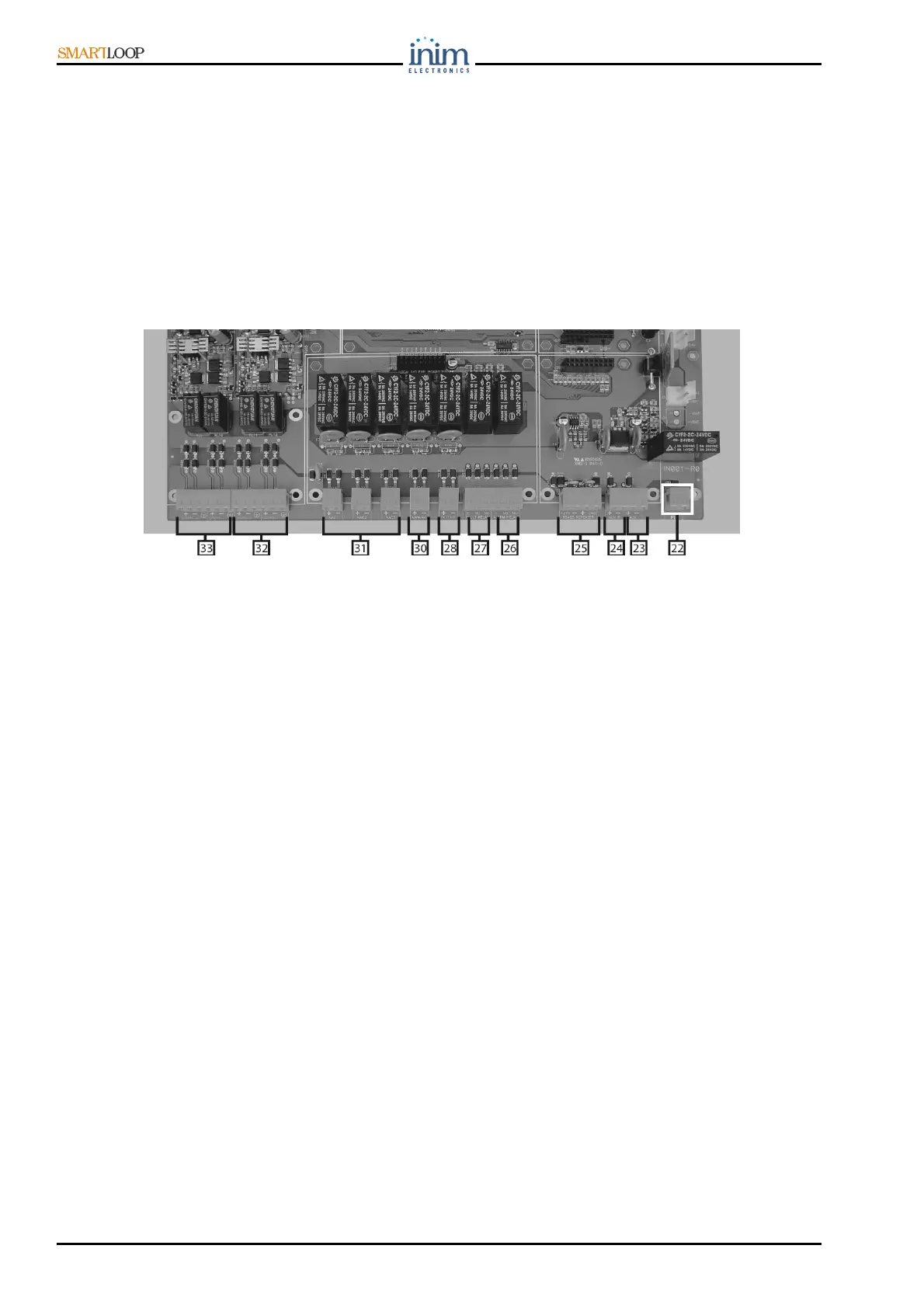
7.3 Description of the motherboard terminals
The numbers in square brackets in this section will help you to identify the components on the
motherboard (see Figure 27).
7.3.1 Terminals
Figure 27 - Terminals
AUX terminals: 24 V output for external loads protected by resettable 1.8A fuse [23]
AUXR terminals:24 V output for external loads protected by resettable fuse 1.8A (with “power cutoff”
during reset) [24]
PL Terminal [22] (comprises terminals PL and GND). PL closes to GND in the event of control panel
shutdown.
RS 485 BUS for the Repeater connections (up to 8) [25]
ALARM relay (dry contact) [26]
FAULT relay (dry contact) [27]
Supervised FAULT NAC output protected by 1 A fuse [28]
Supervised ALARM NAC output protected by 1 A fuse [30]
Supervised, programmable NAC Outputs (NAC1, NAC2, and NAC3) protected by 1 A fuse [31]
Loop 2 In/Out terminals [32] (6 terminals, 3 Input terminals and 3 Output terminals)
Loop 1 In/Out terminals [33] (6 terminals, 3 Input terminals and 3 Output terminals)
7.4 Loop Connections
The loops accommodate a vast array of fire system devices (detectors, manual callpoints, fire buttons,
Input and Output modules, etc.).
For a detailed description of the devices the Loop accepts, refer to Appendix B.
Due to electrical incompatibility (refer to Appendix B), different brand devices (i.e. devices using
different protocols) cannot co-exist on the same loop. However, the loops can be programmed
separately in such way as to allow the system to manage different brand devices on different loops.