Installation Manual
40 Connections
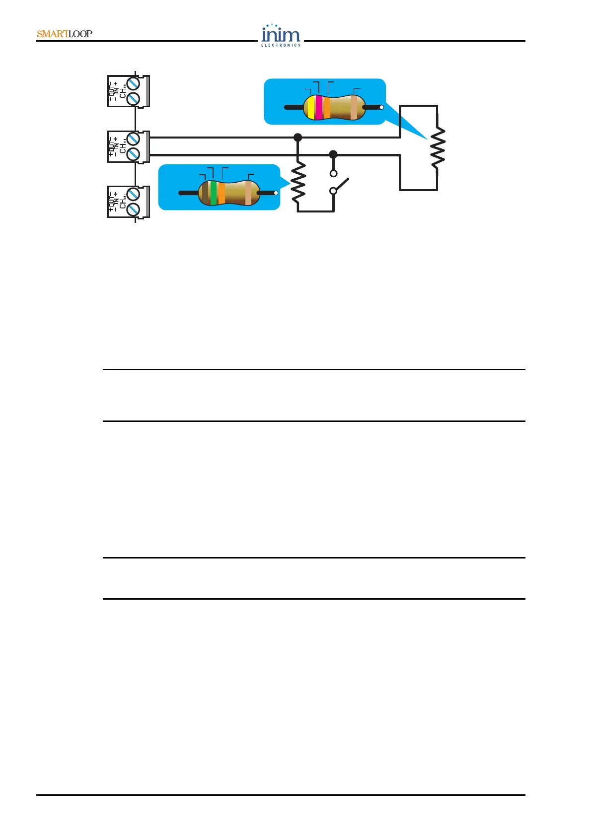
• Supervised Input
Figure 37 - Supervised Input
7.16 Connecting to a PC or serial printer
The panel can be connected:
• permanently to a PC equipped with monitoring software;
• temporarily to a PC during system configuration sessions (for uploading/downloading).
The panel can be connected via:
• RS232 port
•USB port
• Ethernet port (if the system is equipped with a SmartLinkLAN board)
Note: Use of one of these ports automatically excludes use of the others.
The communication ports are opto-isolated in order to allow permanent connection to a PC or
printer.
7.17 Connecting a SmartLinkLAN board equipped panel to a PC
In this case, the RS232 and USB port will not be available for use. Therefore the PC must be
connected to the Ethernet port on the SmartLinkLAN board by means of a cross patch-cord.
7.18 Connecting a serial printer
1. Connect the serial printer to the RS232 port.
2. Using the Print option from the panel display menu, enable the printer to communicate with the
panel.
Note: If you intend disconnecting the serial printer from the RS232 port in order to connect a PC, it will
be necessary to DISABLE the serial printer before doing so. If you do not DISABLE the serial
printer, the PC will be unable to communicate with the panel.
7.19 Batteries
The panel cabinet provides housing for two 12 V / 17 Ah internal batteries.
Once powered up, the panel will recharge and monitor the batteries automatically, as follows.
7.19.1 Efficiency testing
The panel checks the efficiency of the batteries at 60 second intervals, by simulating load current
demand (as required during mains black-out). If the batteries fail to meet the demand, the event will
be indicated on the respective Fault LED and on the display.
BROWN
GREEN
ORANGE
GOLD
15K
7
YELLOW
VIOLET
ORANGE
GOLD
47K
7