Installation Manual
38 Connections
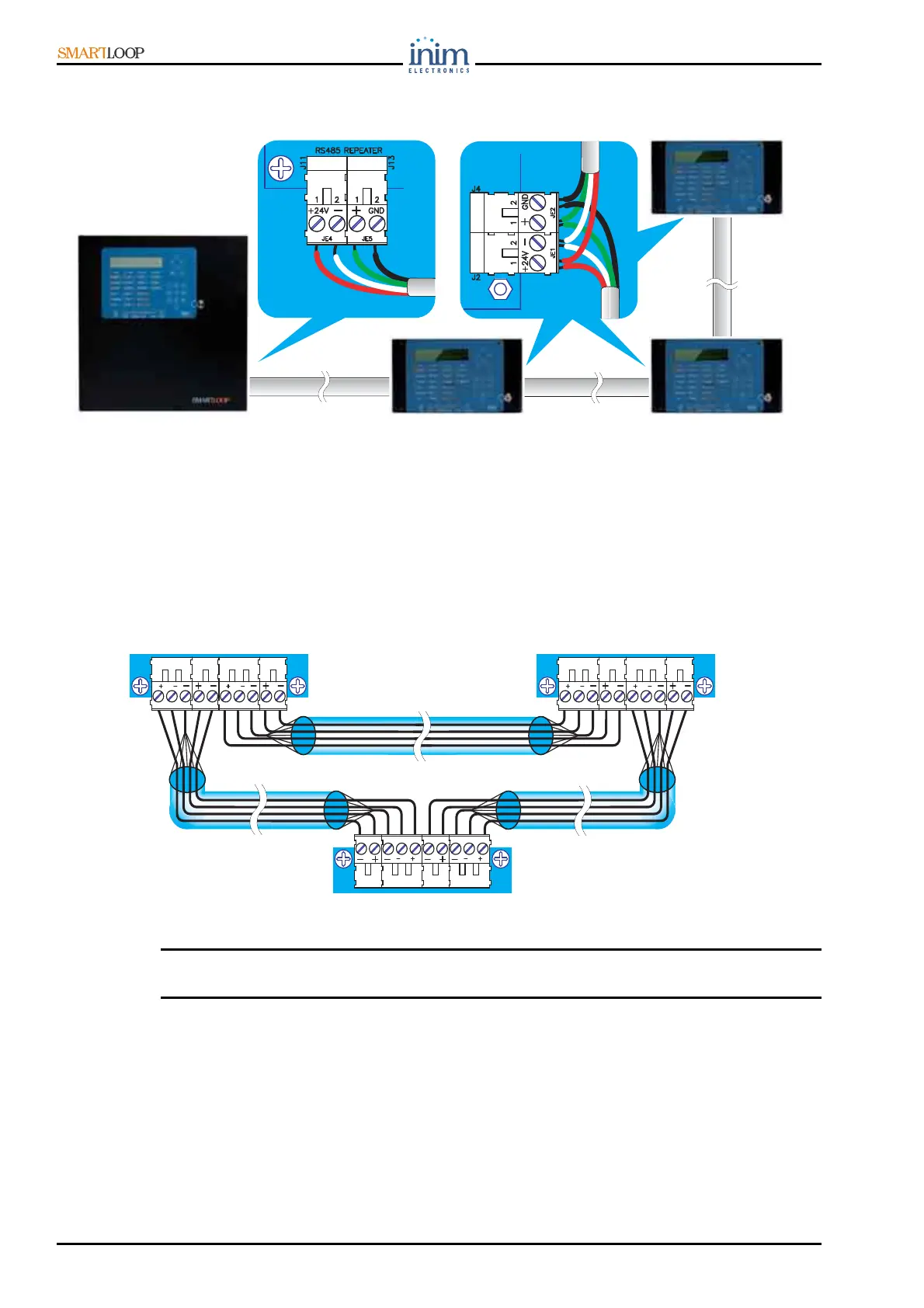
7.13 Connecting Repeater panels to the RS 485 bus
The RS 485 BUS accepts up to 8 Repeater panels.
Figure 32 - Connecting Repeater panels
1. Use 4-pole shielded twisted cable for the connections.
2. Connect the Repeater panels in parallel to the RS 485 bus.
3. Insert the jumper in EOL position on the last Repeater panel only (as shown in Figure 42).
The maximum wire length of the RS485 BUS is 1000 meters.
7.14 Connecting the SmartLoopNET module
Use either 4 pole shielded twisted cable for the connections or Cat 5 STP cable for Ethernet
connections. The latter will allow you to wire the data communication ring and the emergency alarm
ring (see the Figure below).
Figure 33 - Connecting the SmartLoopNET module
Danger: In order to allow the ring to operate properly, the Port-B and Alarm-B terminals must
be connected to the successive Port-B and Alarm-B terminals.
The control panel uses an RS-485 BUS for the HorNet ring node to node communications. The RS-485
BUS communicates at speeds of up to 57600 baud over distances up to 2000 metres between two
nodes. The SmartLoop/NET ports are opto-isolated, as without isolation the connection to the data
acquisition hardware to the target carries the potential for creating ground loops which will cause
excessive noise in the signal.
7.15 Connecting the SmartLoop/INOUT Board
Each of the terminals on the SmartLoop/INOUT board can be configured in one of the following ways:
DD
PORT- A
ALARM- A
DD
PORT- B
ALARM- B
DD
PORT- A
ALARM- A
DD
PORT- B
ALARM- B
DD
PORT- A
ALARM- A
DD
PORT- B
ALARM- B