Installation Manual
Internal devices 23
4.7 The SmartLoop/INOUT board
The SmartLoop/INOUT board provides 6 outputs (CH1 - CH6). Each of which can be configured as a:
Supervised Output (NAC - 1 A max.), Supervised Input, Conventional detector line or Gas detector
line. During the programming phase, you can program the events which will activate the outputs and
the actions generated by the inputs.
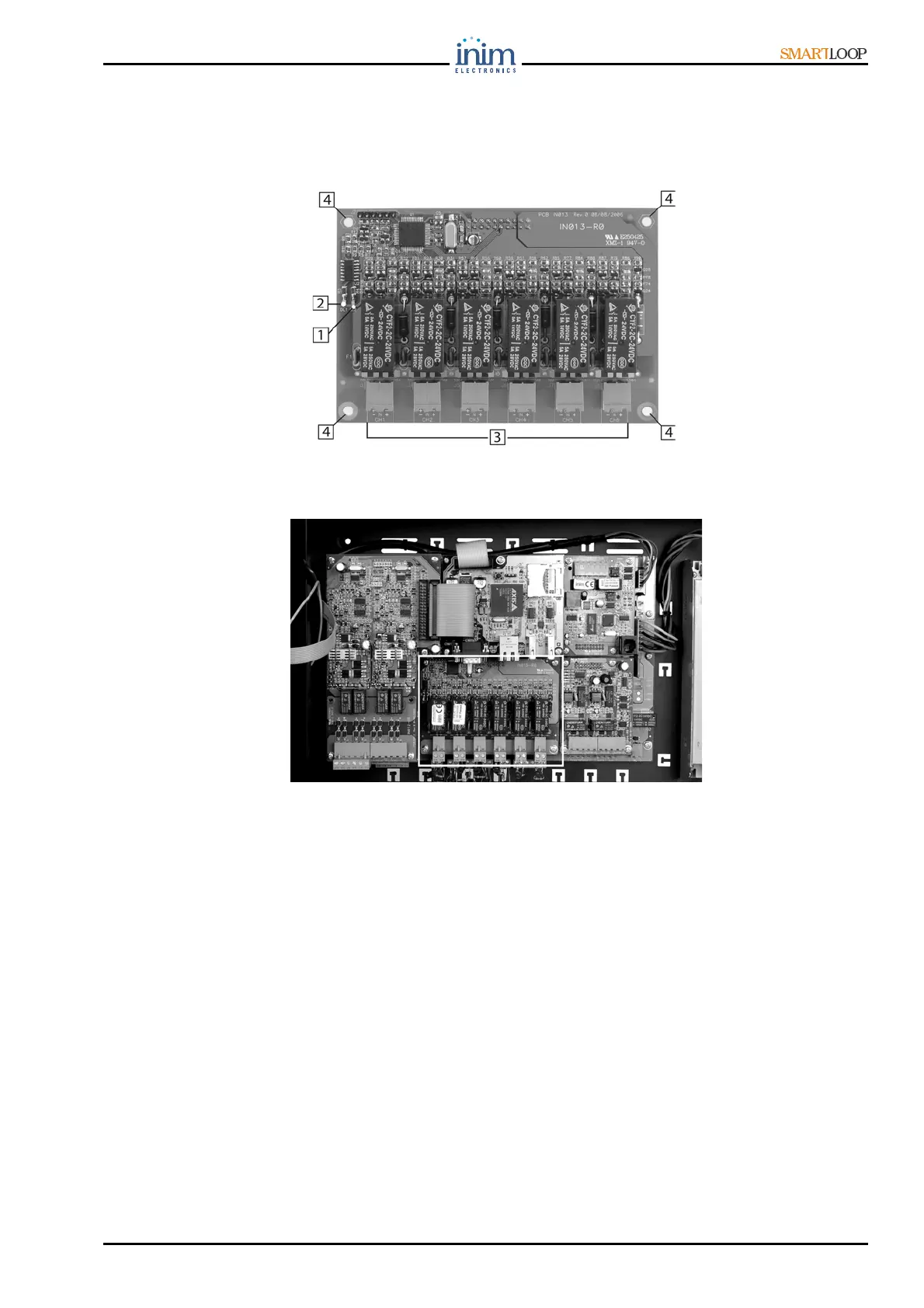
Figure 15 - The SmartLoop/INOUT board
Figure 16 - The SmartLoop/INOUT board location on the motherboard
4.7.1 The SmartLoop/INOUT board components
1. Activity LEDs (2)
2. Fault LED on at least 1 of the 6 board channels
3. Input/Output terminals
4. Board screws (4)
4.8 SmartLetUSee/LED module
The SmartLetUSee/LED can be used with “/P” models only. It fits directly to the frontplate door, and
connects to the keypad/display board. It has 48 red zone status LEDs that provide the signals defined
during the configuration phase.