Installation Manual
Installation 29
Chapter 6
Installation
Danger: Installation of this fire control panel must be carried out in full respect of the local fire
codes, laws and bylaws in force, and in accordance with the instructions and guidelines
herein.
The cable glands must be rated UL94-V1 flame class (or higher)
6.1 Choosing the mounting location
This Fire control panel should be located in a place that is:
•Dry
• Far from sources of interference, including:
Electrical noise such as electric motors in appliances and heating, and air conditioning units.
The mounting location must satisfy all the requirements of the respective Fire Code, laws and bylaws
in force.
6.2 Installation flow, guidelines and testing
1. Lay the cables
2. Connect the system devices to the loop.
3. Install system peripherals
4. Mount the panel
5. Install accessory modules (if necessary)
6. Power up the system
7. Test the system (network, repeaters, ancillary and signaling devices).
Danger: DO NOT apply mains power until all connections have been completed.
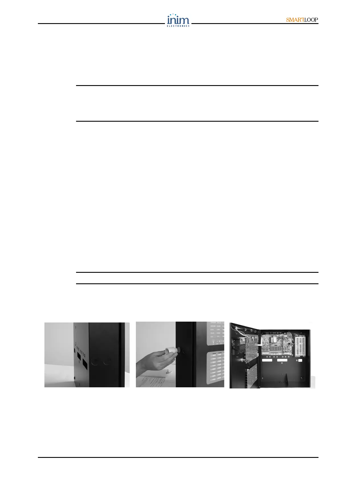
6.2.1 Wall mounting the panel
Figure 23 -
Wall mounting the panel