Installation Manual
Internal devices 19
7. Board screws (5)
4.4 The SmartLoop/NET board
The SmartLoop/NET board will allow you to create a token-ring network (see “Example configuration:
6 node token-ring network layout”) of up to 30 control panels by means of a 3-pole cable with a
locking ring. The maximum cable length of 2000 meters (allowed between each control panel)
provides a highly fault-tolerant network. Using a supplementary 2-pole cable (5 poles in all), you can
create a protection ring which can pass alarm conditions, coming from a fire control panel with
microprocessor fault, through the ring.
Danger: In order to allow the ring to operate properly, the Port-B and Alarm-B terminals must
be connected to the successive Port-B and Alarm-B terminals.
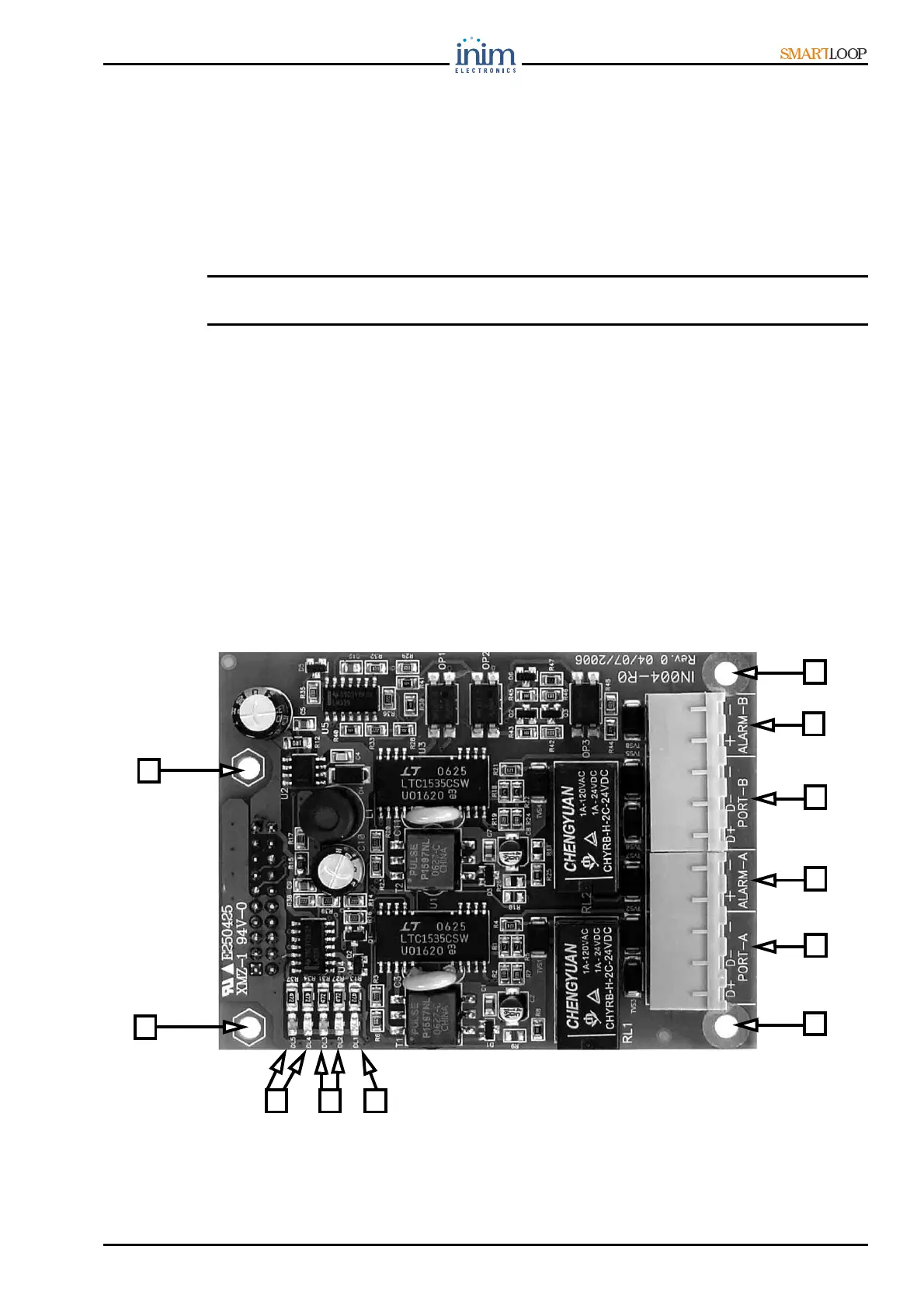
4.4.1 The SmartLoop/NET board components
1. A terminals: for the protection-ring connection (to be connected to Alarm-B of the successive
control panel)
2. Communication Port A (to be connected to Port-B of the successive control panel)
3. In-ring LED (indicates the In Service/Out of Service status of the SmartLoop/NET board. If this
LED is Off, the panel is isolated from the HorNet environment.
4. Port A status LEDs (2)
5. Port B status LEDs (2)
6. B terminals: for the protection-ring connection (to be connected to Alarm-A of the previous control
panel)
7. Communication Port B (to be connected to the Port-A terminals of the previous control panel)
8. Board screws (4)
Figure 9 - The SmartLoop/NET board
8
8
2
1
7
6
8
8
5 4 3