Installation Manual
Connections 35
Note: Each loop output conductor must be fitted with a split ferrite core (included), as shown in the
figure below.
Figure 28 - Attaching the split ferrite core to loop output cables
7.5 Loop terminals
Loop1 Output (terminal “+” and “-”): connect all loop devices in parallel to these terminals, in
accordance with the specific device instructions.
Earth*: connect the shield of the STP cable (2 pole) to this terminal.
Note: Always leave one end of the shield disconnected.
Loop1 Input (terminal “+” and “-”): connect the return loop wiring to these terminals.
These terminals allow the panel to check the loop integrity. In the event of a single interruption on the
circuit, the panel will communicate with the isolated trunk elements via these terminals.
Earth*: connect the shield of the STP cable (2 pole) to this terminal.
Note: Always leave one end of the shield disconnected.
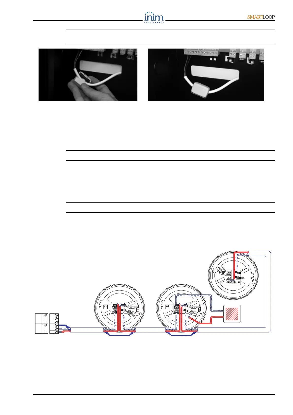
7.6 Connecting devices to the Loop
The loop devices can be 2-wire (open loop) or 4-wire (closed loop) connected.
Use 4-pole shielded twisted cable or shielded twisted pair cable (2 pole). For the wire sizing, refer to
Appendix B.
Figure 29 - 2 wire connection
If you are using a 4 wire connection, connect the STP cable shield to one end of the loop and leave the
other end disconnected.
FI100
REMOTE
LED
+
-
LOOP-I
LOOP-O
VB100 VB100
BLR100