Installation Manual
Installation 31
4. Using the screws (previously removed), secure the board to its location.
6.2.4 Flat cable to motherboard attachment boards (SmartLoop/2L or SmartLAN)
1. Remove the respective screws on the motherboard (see the figure for the location of the board
concerned).
2. Screw in the metal board supports (supplied with the board).
3. Connect one end of the flat cable (supplied) to the motherboard.
4. Fit the attachment board to the supports and, using the screws (previously removed from the
board) secure it in place.
5. Using the other end of the flat cable, connect the attachment board to the motherboard.
Note: You must insert the 2032 lithium battery into its holder (with “+” sign facing you) before
connecting the SmartLAN board. This battery guarantees data retention.
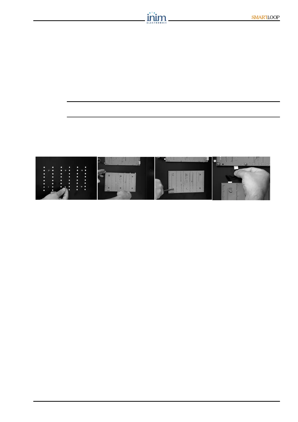
6.3 Connecting the SmartLoop/LED module
Figure 25 - Connecting the SmartLoop/LED module
1. Fit the plastic spacers to the soldered screws on the back of the cabinet door.
2. Locate the SmartLoop/LED module in position.
3. Using the nuts (supplied), secure the board to its location.
4. Using the flat cable, connect the SmartLoop/LED module to the Keypad/Display module.
1
2
3
4